


Column Designer
Quick Guide
Overview of Column Designer
Column Designer is a comprehensive web-based software package for the analysis and design of concrete, reinforced concrete, and composite concrete columns. It supports direct design and advanced analysis-based workflows, enabling engineers to evaluate column behavior under axial force, bending, and slenderness effects.
Key Capabilities
Column Designer provides the following core capabilities:
Guided column design using the Quick Design Wizard
Import of columns directly from ETABS, including materials, sections, loads, and framing
Design in accordance with 14+ international design codes, including ACI 318-19, Eurocode 2, and AASHTO LRFD
Support for sway and non-sway conditions with automatic slenderness calculations
Automatic reinforcement optimization using the Auto Design feature
Generation of P-M interaction surfaces, moment-curvature curves, and capacity ratio reports
Design reports with user-added text
Key Terminology
| Term | Definition |
|---|---|
| Project File | A file where columns are saved and managed. Multiple columns can be stored in a single Project File. |
| Column | A complete structural member consisting of a cross-section, framing conditions, and load combinations. |
| Section | A combination of one or more shapes forming a single cross-section. Analysis is performed at the section level. |
| Shape | The basic geometric component used to build sections. Shapes can be concrete, steel, or user-defined. |
| Base Rebar Pattern | The primary rebar layout required for magnified moment calculations. Assigned under the Property Grid. |
| Auto Design | An iterative tool that optimizes reinforcement layout based on user-defined design rules and code limits. |
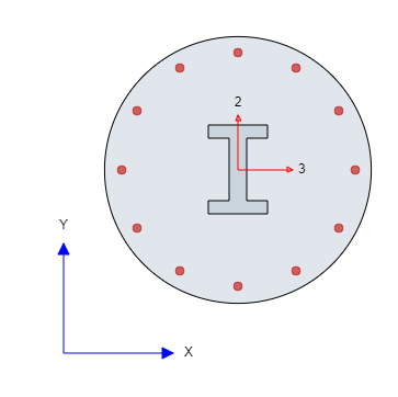
Figure: Section composed of two shapes
Operating Modes
Column Designer operates in three distinct modes that control what actions are available:
Selection Mode: Activated from Edit Menu. Shapes can be selected and edited via the Property Grid, but not drawn directly.
Drawing Mode: Activated when a draw tool is selected. The cursor changes to a “+” symbol. Exit by pressing Esc.
Results Mode: Activated from the Results Menu or Project Explorer. Section editing is disabled while viewing results.
The Column Designer Interface
Home Screen
When Column Designer is launched, the home screen is organized into the following areas:
Quick Design Wizard: A step-by-step guided panel at the top of the screen. Recommended starting point for new users.
Templates: Four ready-to-use project templates (Building Frame Column, Bridge Pier, Shear Wall, Retrofit Assessment).
New Column: Options to start with From ETABS, Rectangular, Circular, or Blank models.
Navigation Panel: Left sidebar for project-level actions and ETABS Extractor installation.
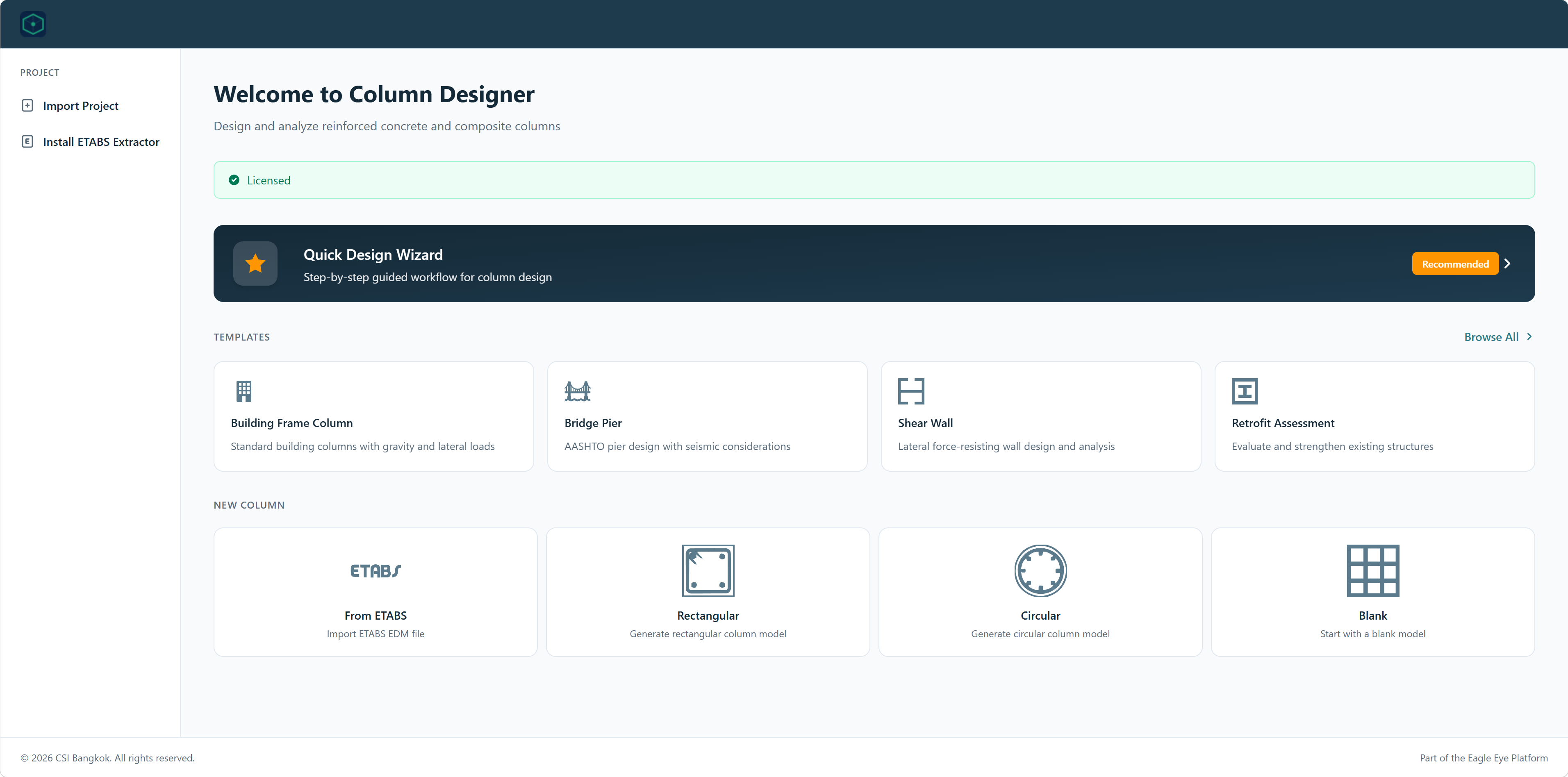
Figure: Column Designer home screen
Working Window Components
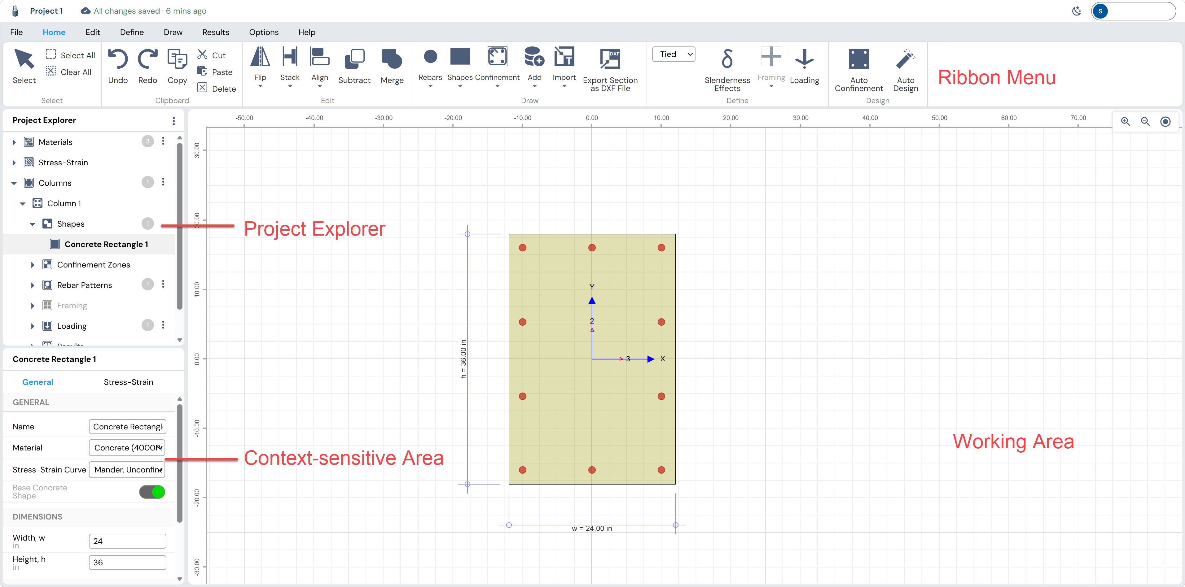
Figure: Column Designer Working Window
| Component | Description |
|---|---|
| Ribbon Menu Bar | Contains all program menus: File, Home, Edit, Define, Draw, Results, Options, and Help. |
| Working Area | The main drawing canvas where shapes and sections are created and modified. Displays a graph-paper grid. |
| Project Explorer | Sidebar with four views: Materials, Stress-Strain, Columns, and Report. Provides structured access to project data. |
| Context-Sensitive Area | Displays grids and panels that change based on the selected tool or object. Includes the Property Grid for editing properties without opening extra dialogs. |
Customizing the Program
Program-wide settings are accessible from Options Menu and apply globally to the current Project File:
Units: Select US Customary or Metric SI.
Design Code: Select the applicable design standard. Changing the code erases all previously generated results.
Number Formatting: Control decimal places, separators, and exponential notation.
View Options: Toggle visibility of grid, ruler, dimensions, and global/local axes.
Diagram Options: Control number of curves and data points on interaction diagrams.
Strength Reduction Factors: Modify capacity reduction factors used for P-M interaction curves.
Interface Theme: Switch between light and dark display themes via Options Menu > General > Theme.
Rebar Sets: Add or remove rebar sizes. Import from standard libraries such as ASTM.

Using Column Templates
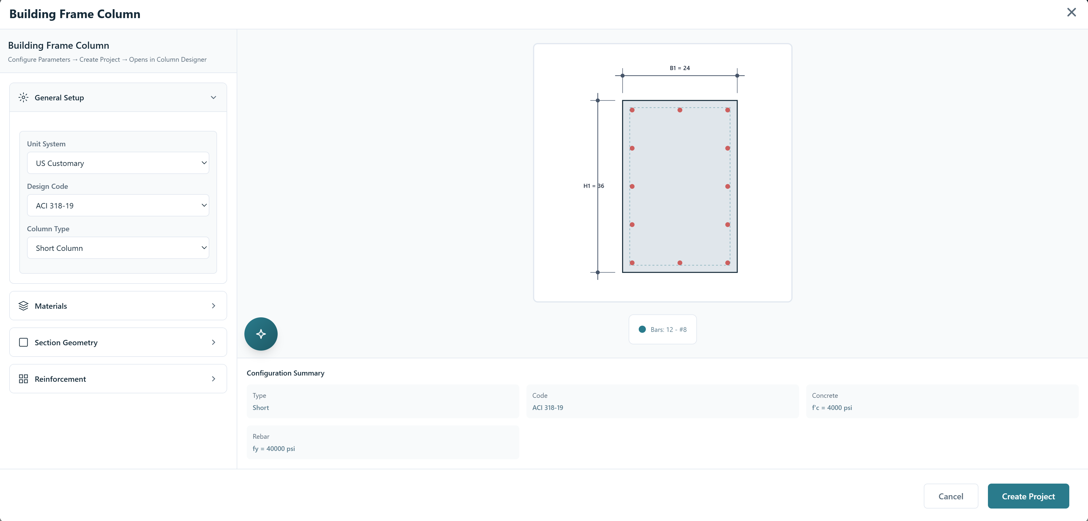
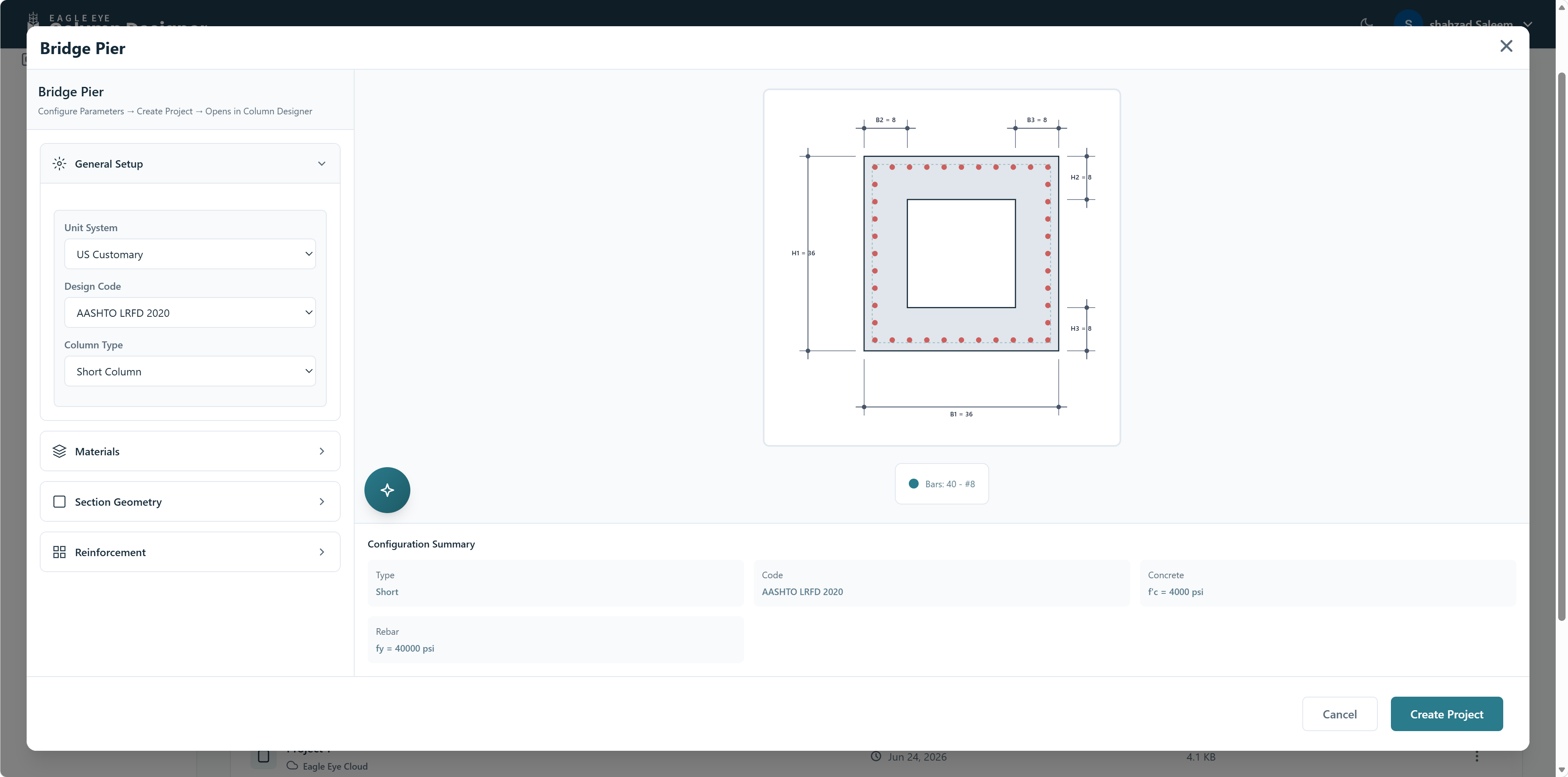
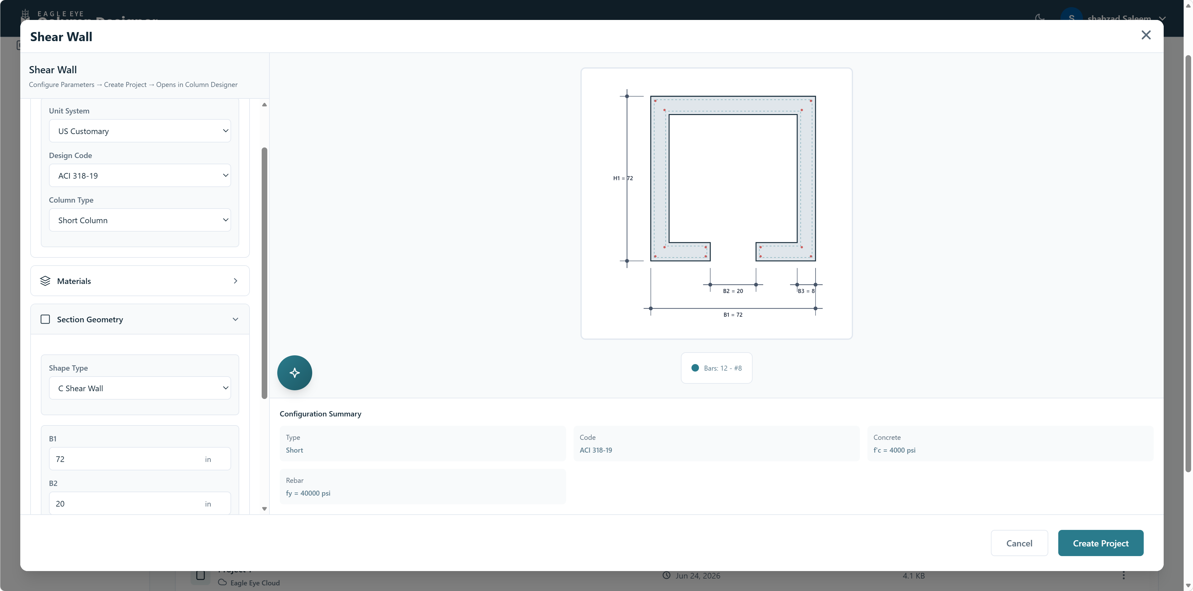
Column Designer provides four ready-to-use templates that pre-configure the relevant parameters for specific column types. To use a template, select it from the home screen. A configuration dialog opens where parameters can be reviewed and adjusted before the project is created.
All templates include: General Setup (units, design code, column type), Materials, Section Geometry, and Reinforcement. A live cross-section preview updates in real time as parameters are adjusted.
Building Frame Column Template
Intended for standard reinforced concrete columns in building structures subjected to gravity and lateral loads. The Configuration Summary at the bottom of the dialog provides a quick overview of key settings.
Bridge Pier Template
Configured for AASHTO pier design with seismic considerations. Uses AASHTO LRFD as the default design code. Configuration sections follow the same structure as the Building Frame Column template.
Shear Wall Template
Configured for lateral force-resisting wall design and analysis. General Setup, Materials, and Reinforcement sections follow the same structure as other templates.
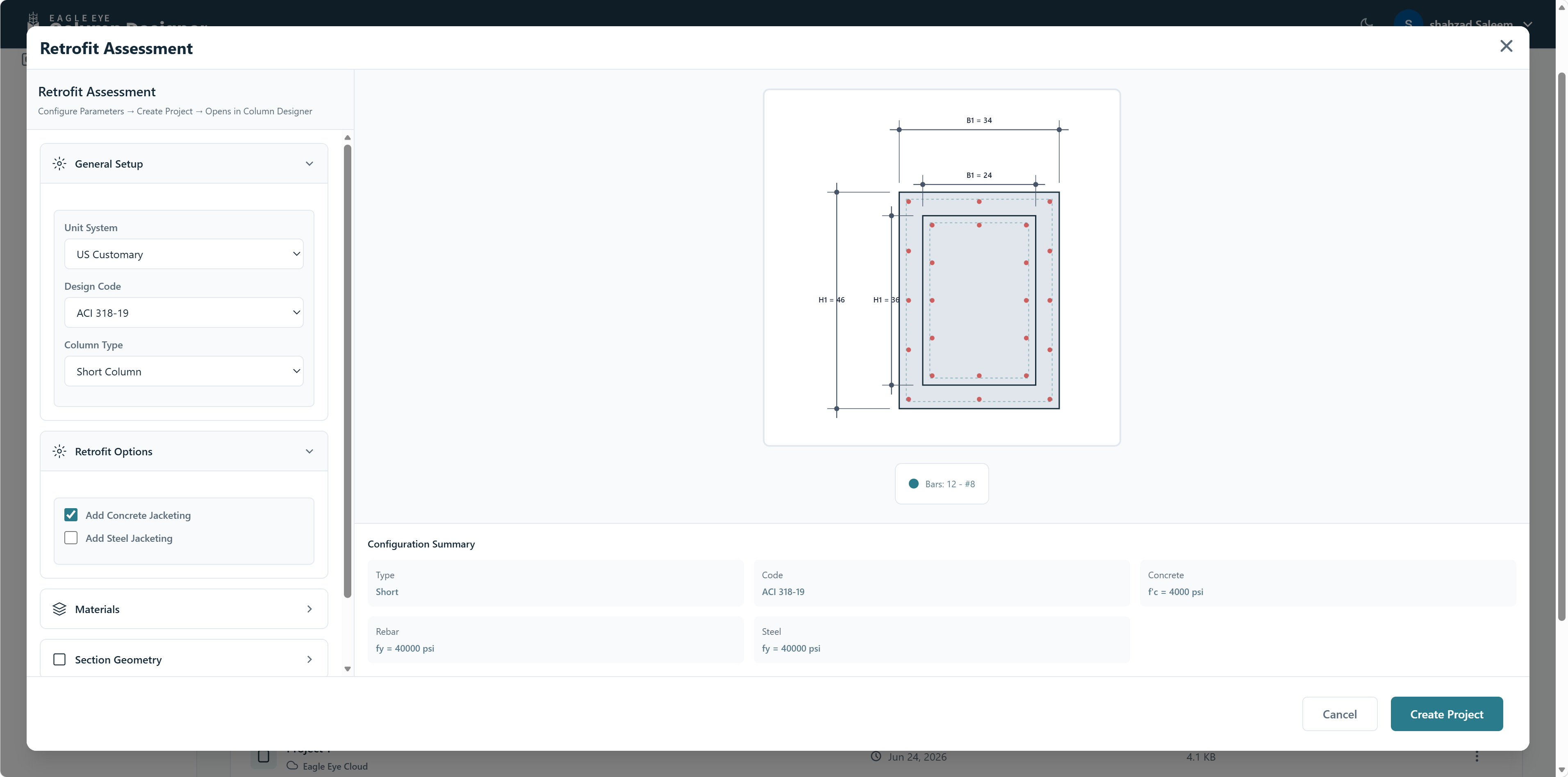
Retrofit Assessment Template
Designed for evaluating and strengthening existing column structures. Includes an additional Retrofit Options section with the following strengthening methods:
Add Concrete Jacketing: Adds a concrete jacket layer around the existing section.
Add Steel Jacketing: Adds a steel jacket around the existing section.
The cross-section preview updates to reflect the selected jacketing configuration, showing both the original and retrofitted section dimensions.
Slenderness Effects — Available in All Templates When the column type is set to Long Column, an additional Slenderness Effects section becomes available. This section allows definition of effective length factors for both XZ and YZ planes, with separate values for braced and unbraced conditions, as well as column height and center-to-center length parameters. |
|---|
Creating Columns
Column Designer provides multiple methods for creating column sections. The recommended method depends on column geometry and the design workflow.
Quick Design Wizard (Recommended for Rectangular / Circular Columns)
The Quick Design Wizard provides a complete guided workflow from section definition to results. Access it from the home screen or via File Menu > Quick Design Wizard.
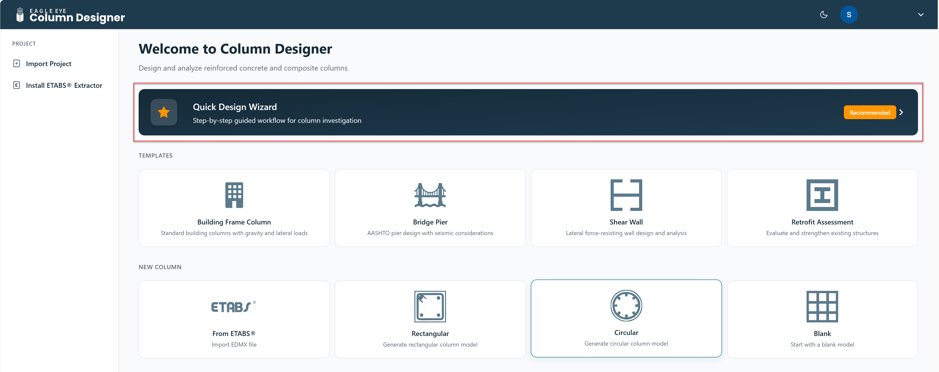
Figure: Quick Design Wizard form
Step 1: Define Project Details: Enter project name, code, engineer, and company. This information appears in detailed report.
Step 2: Set Units and Code: Select working units (US Customary or Metric SI) and the applicable design code.
Step 3: Define Material Properties: Review or enter properties for concrete and rebar using the tabbed material form.
Step 4: Define Section Shape: Select stirrup type (Tied or Spiral) and shape (Rectangular or Circular). Enter dimensions, clear cover, rebar size, and distribution.
Step 5: Enable Slenderness (if applicable): Toggle on Consider Slenderness to account for slenderness effects. This activates the Define Framing button.
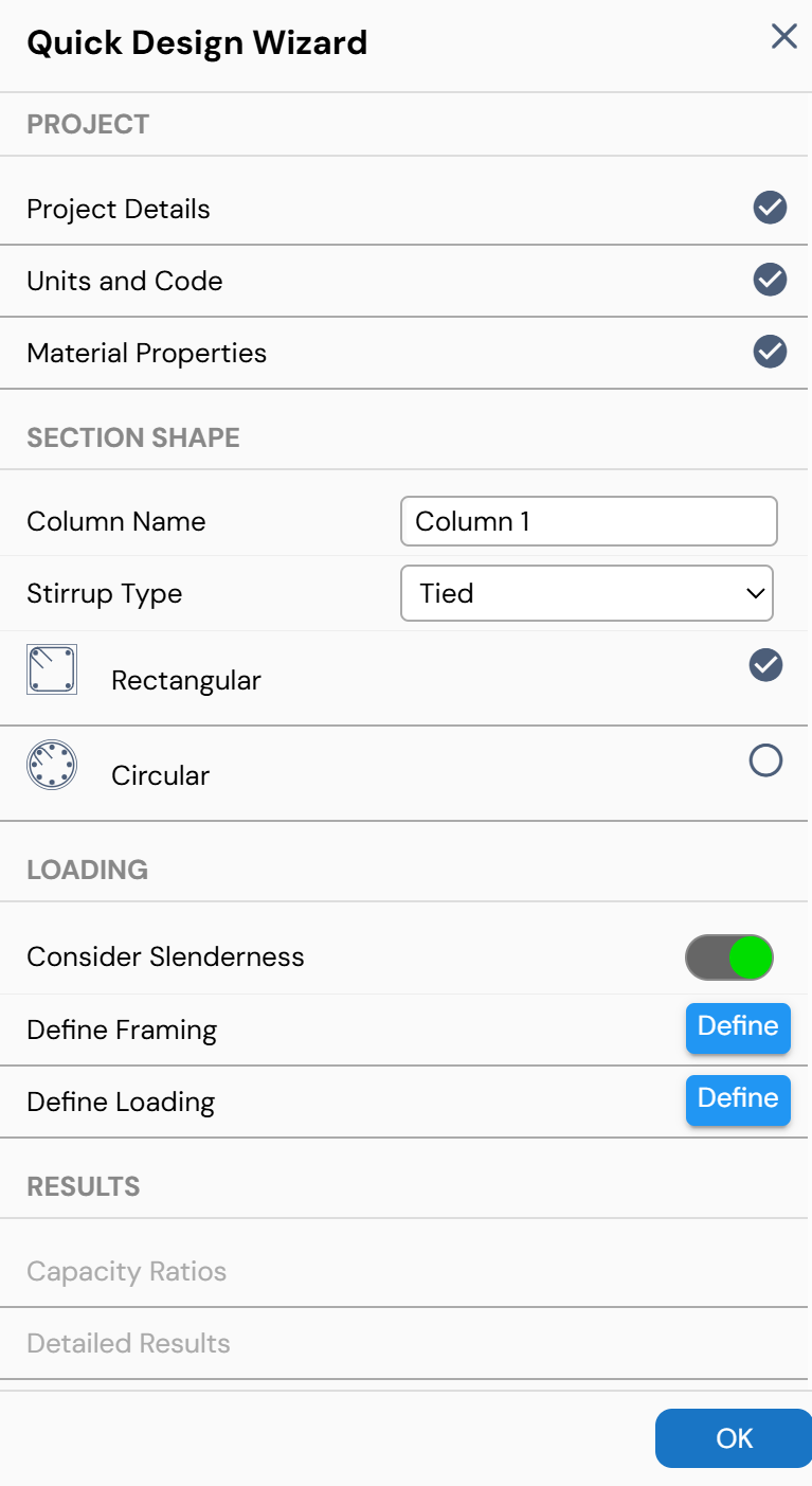
Figure: Quick Design Wizard
Step 6: Define Framing Conditions: If slenderness is enabled, click Define Framing and enter end restraints and effective length factors.
Step 7: Define Loading: Enter column loads. Detailed Loading is displayed automatically for slender columns; Simple Loading for short columns.
Step 8: Review Results: Use the results options in the wizard to view Capacity Ratio, Detailed Results, Interaction Diagrams, or Generate a Report.
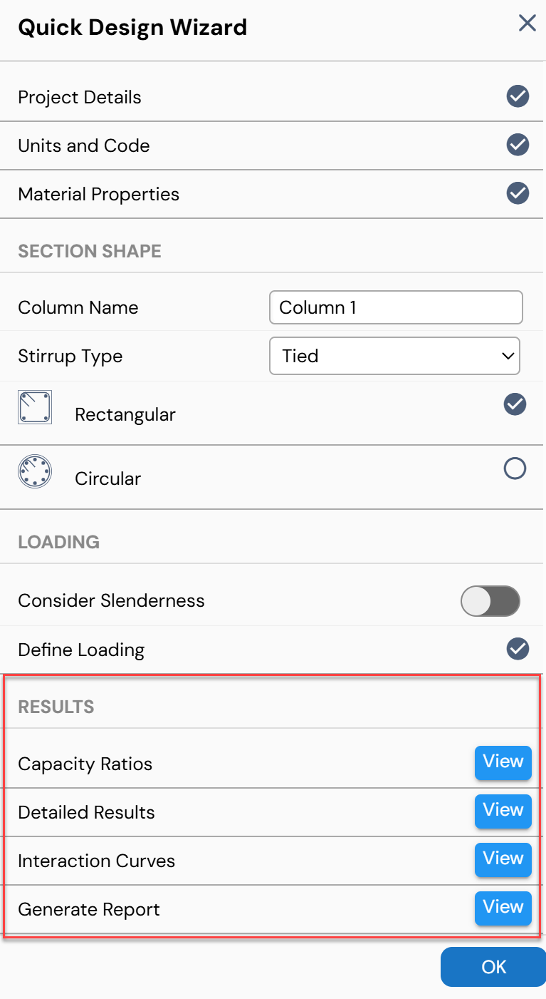
Figure: Results options in Quick Design Wizard
Rectangular and Circular Models
Use New Column Templates or File Menu > Rectangular Model or Circular Model to quickly create a standard column section. After creation, framing, loading, and results are defined through the standard menu workflow.
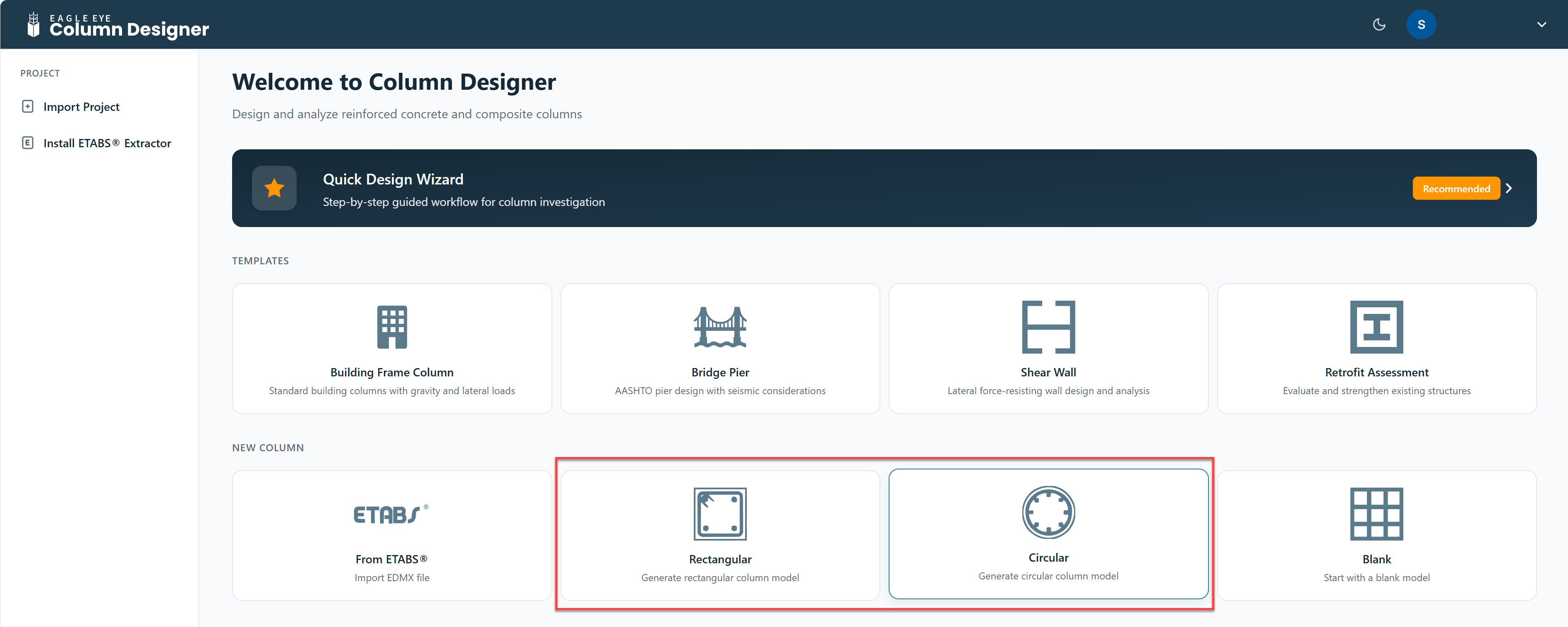
Figure: Creating a Rectangular or Circular column
Step 1: Create Model: Select Rectangular Model or Circular Model from New Column Template or File Menu.
Step 2: Set Units and Code: Modify via Options Menu > General if needed.
Step 3: Define Stress-Strain Models: Define concrete and steel models via Define Menu > Stress Strain.
Step 4: Define Material Properties: Use Define Menu > Project > Materials to specify concrete and rebar properties.
Step 5: Edit Shape / Rebar Properties: Click on the shape or rebar to activate the Property Grid and edit dimensions numerically.
Step 6: Enable Slenderness (if applicable): Define Menu > Slenderness > Slenderness Effects. Then define framing conditions if required.
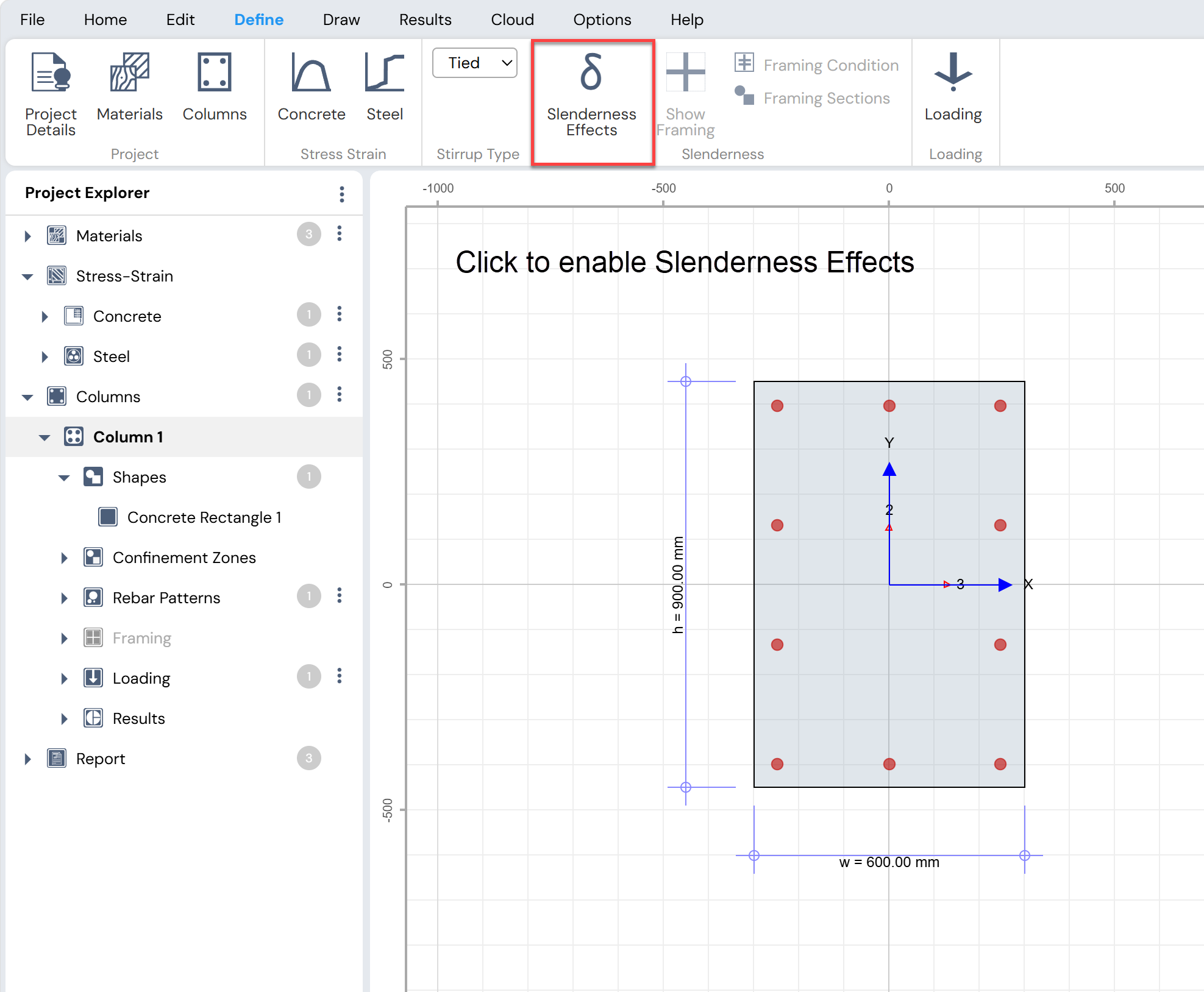
Figure: Enabling Slenderness Effects
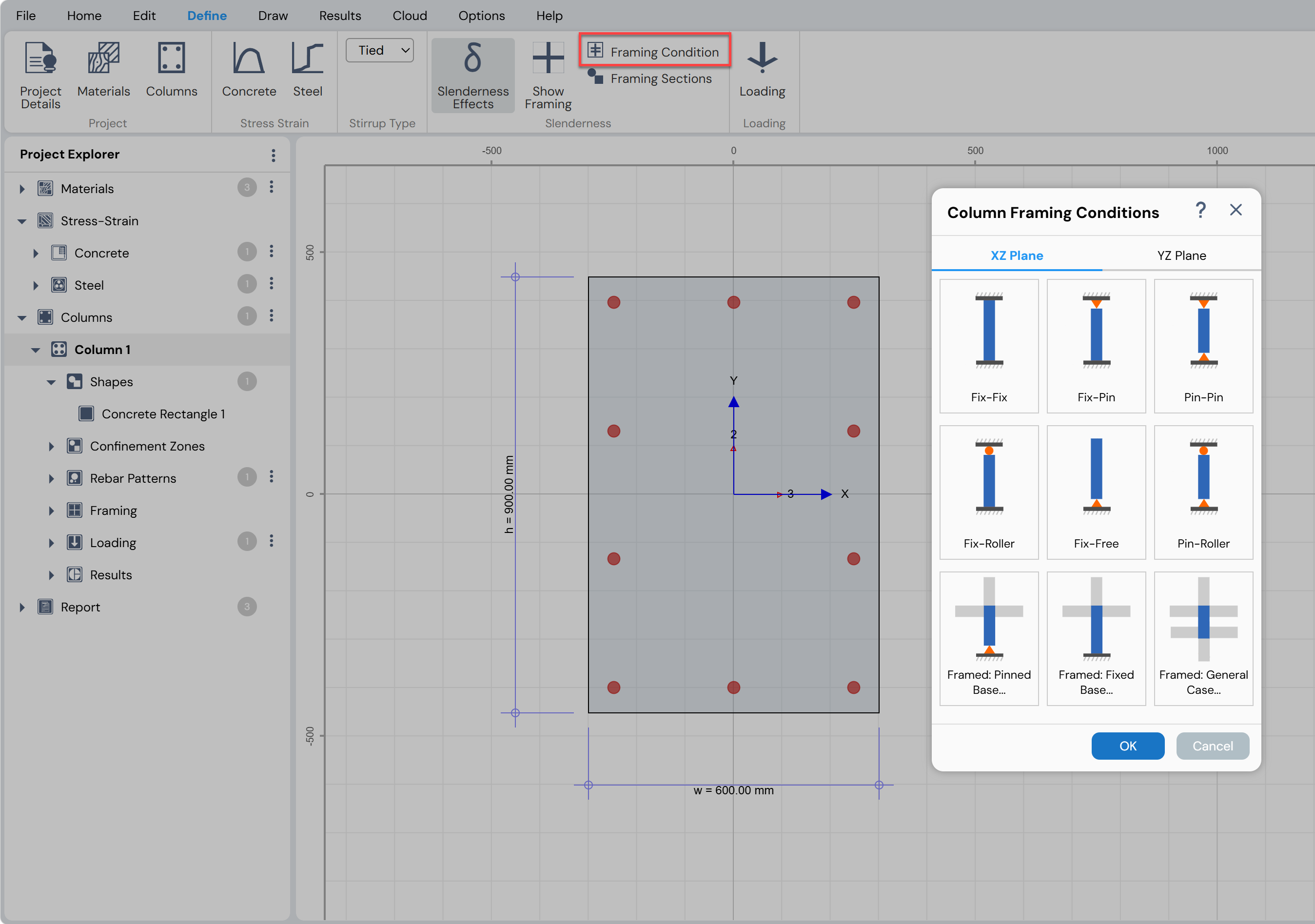
Figure: Framing Conditions for slender columns
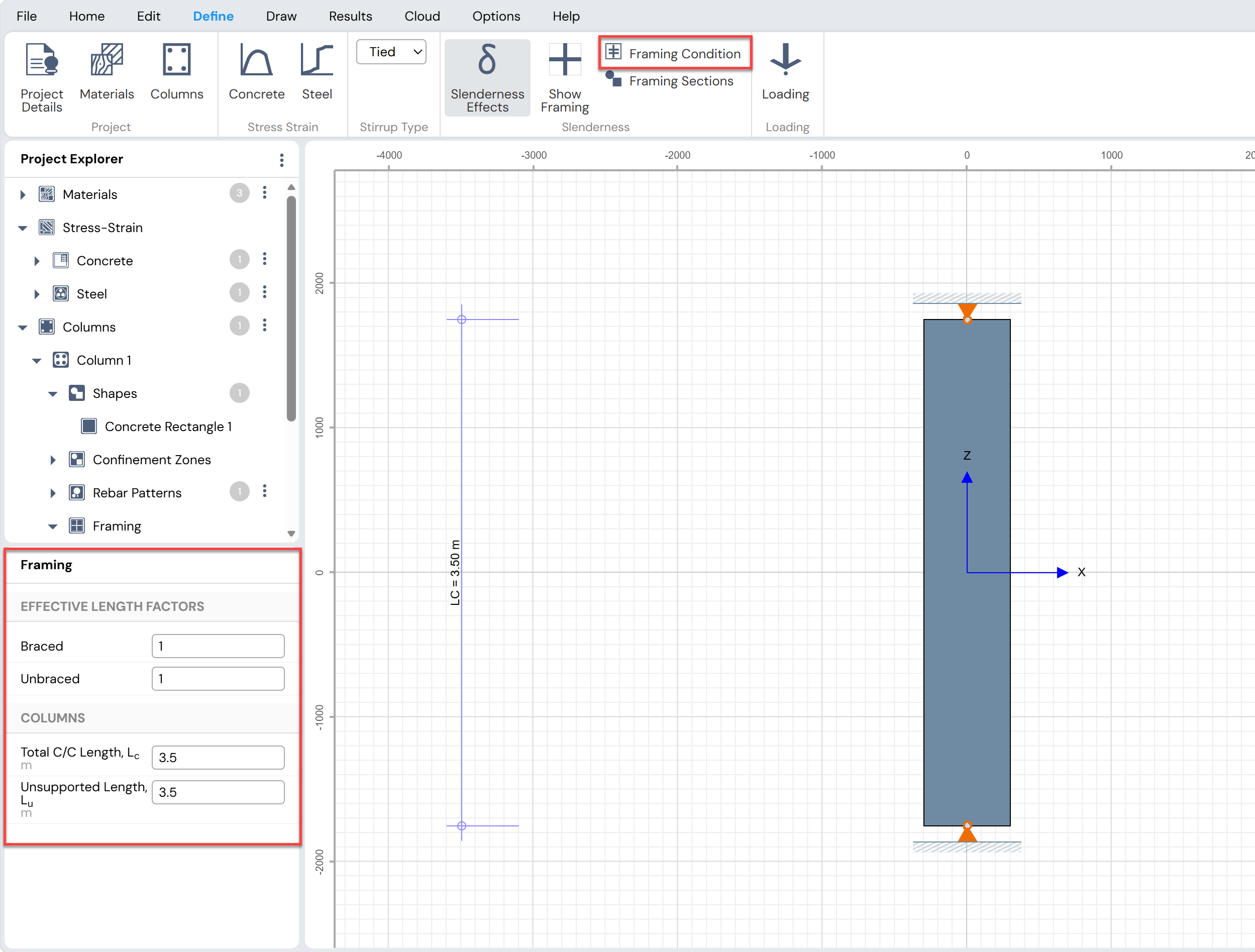
Figure: Effective Length Factors and Column Lengths
Step 7: Define Loading: Use Define Menu > Loading > Loading or Project Explorer > Columns > Loading.
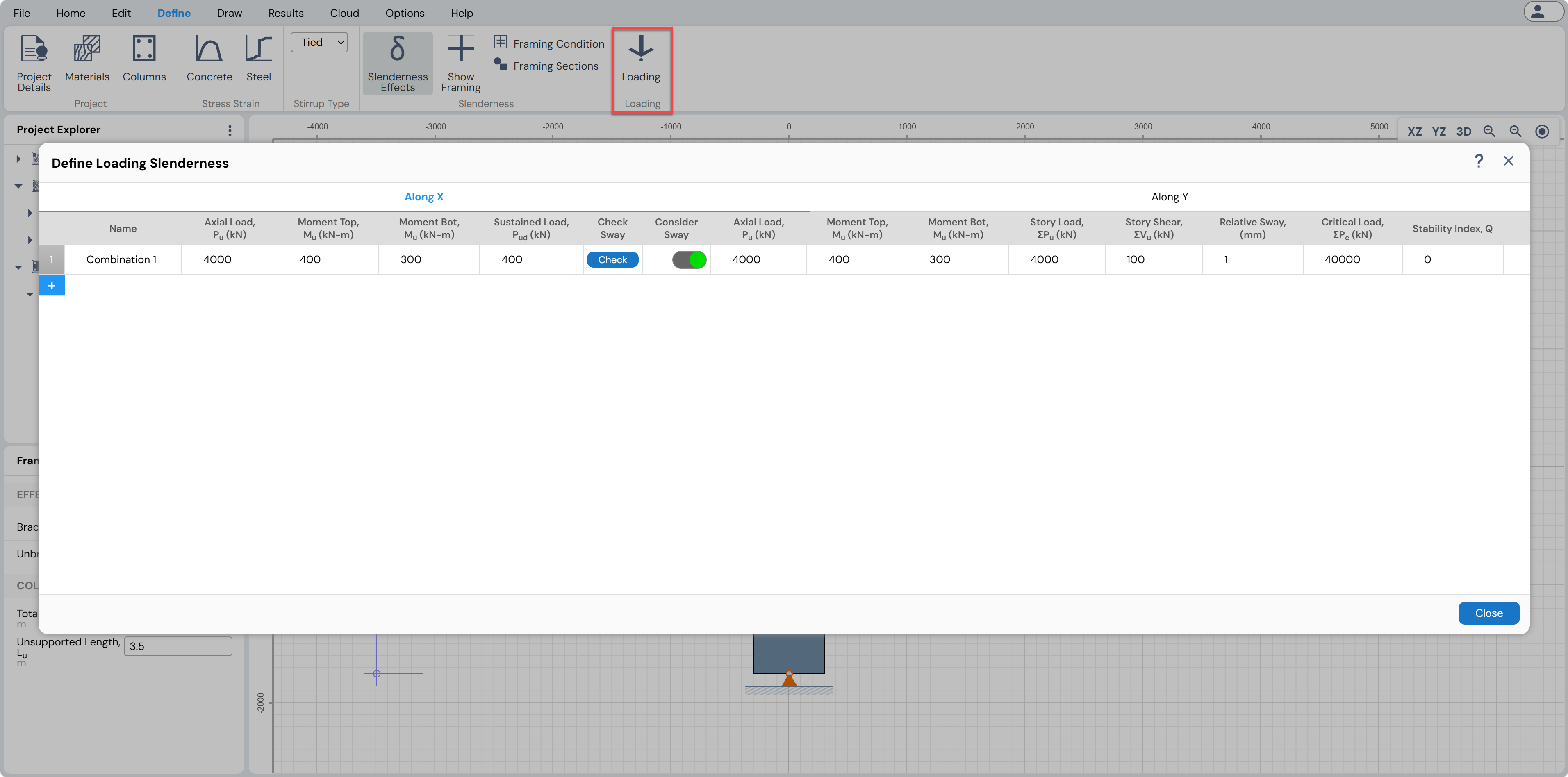
Figure: Load Definition in Column Designer
Step 8: Apply Auto Design: Home Menu > Design > Auto-Design. Optimizes reinforcement for the governing load combination.
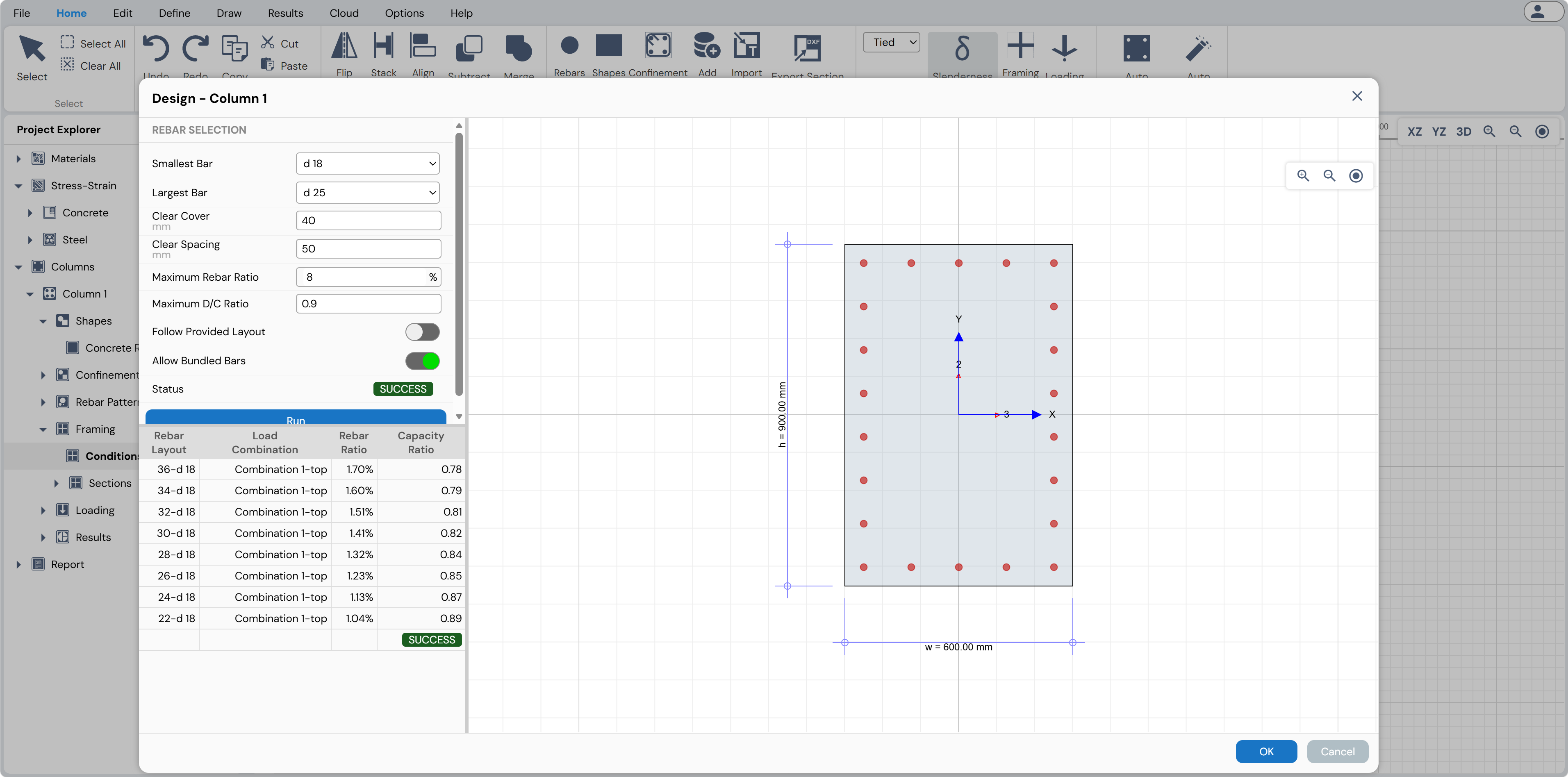
Figure: Auto Design Feature
Step 9: Review Results: Access outputs from Results Menu or Project Explorer > Columns > Results.
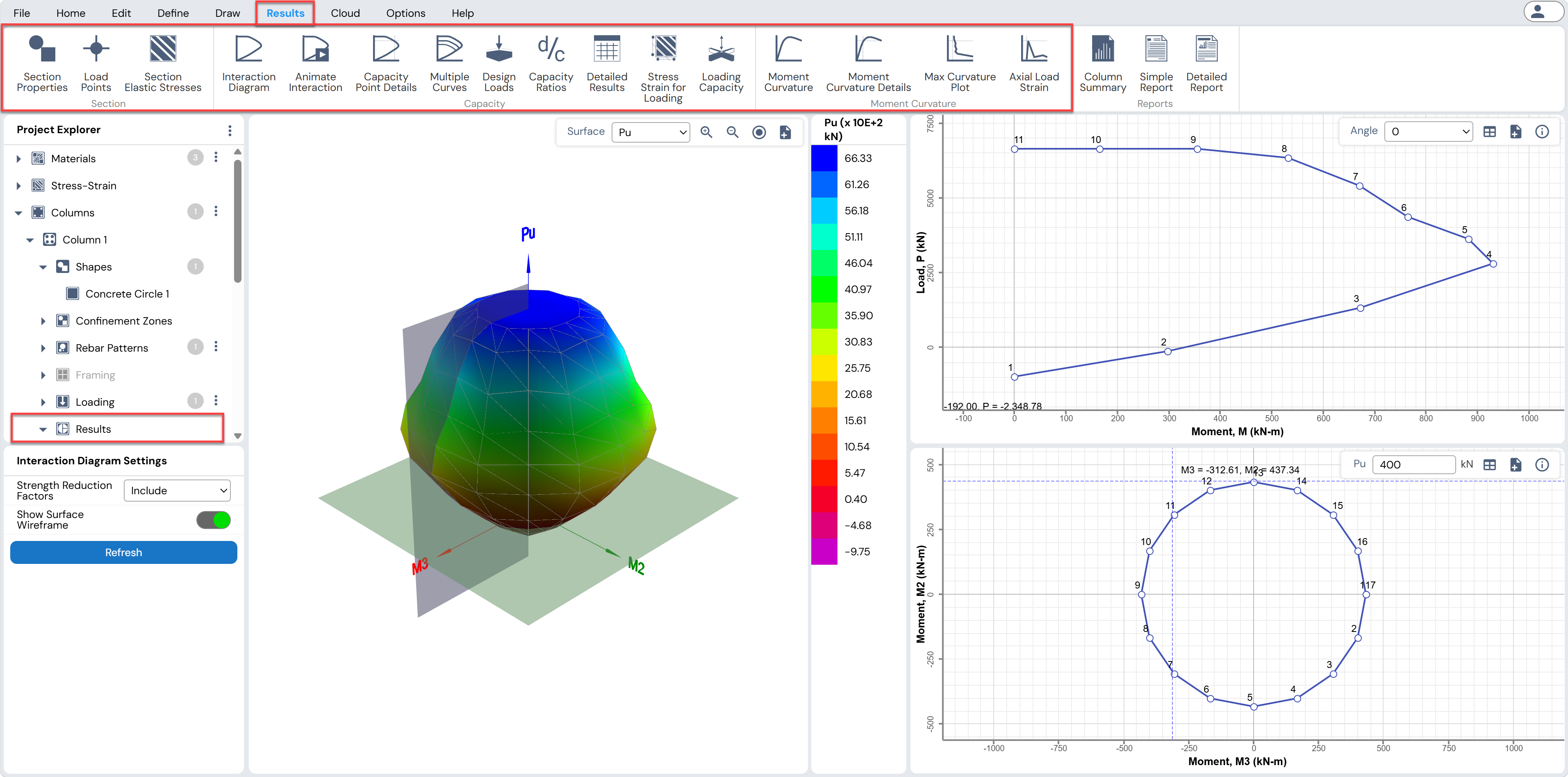
Figure: Viewing Result Options
Step 10: Generate Report: Use the Report view in Project Explorer to generate summary or detailed reports.
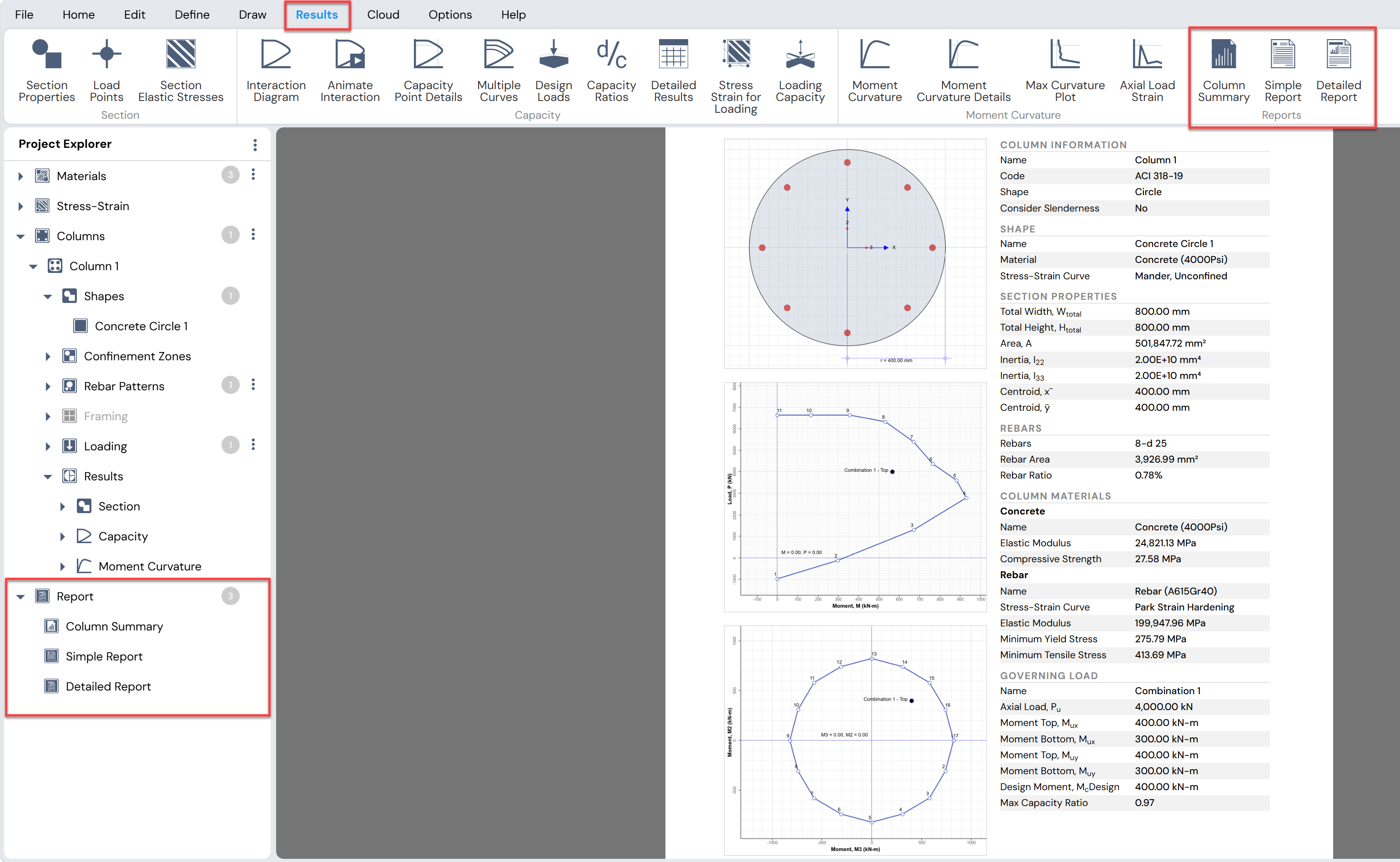
Figure: Various reports generated in Column Designer
Blank Model (Custom Sections)
Use Blank Model from New Column Section or File Menu > Blank Model to create a column of any geometry. This method provides maximum flexibility for non-standard or complex sections.
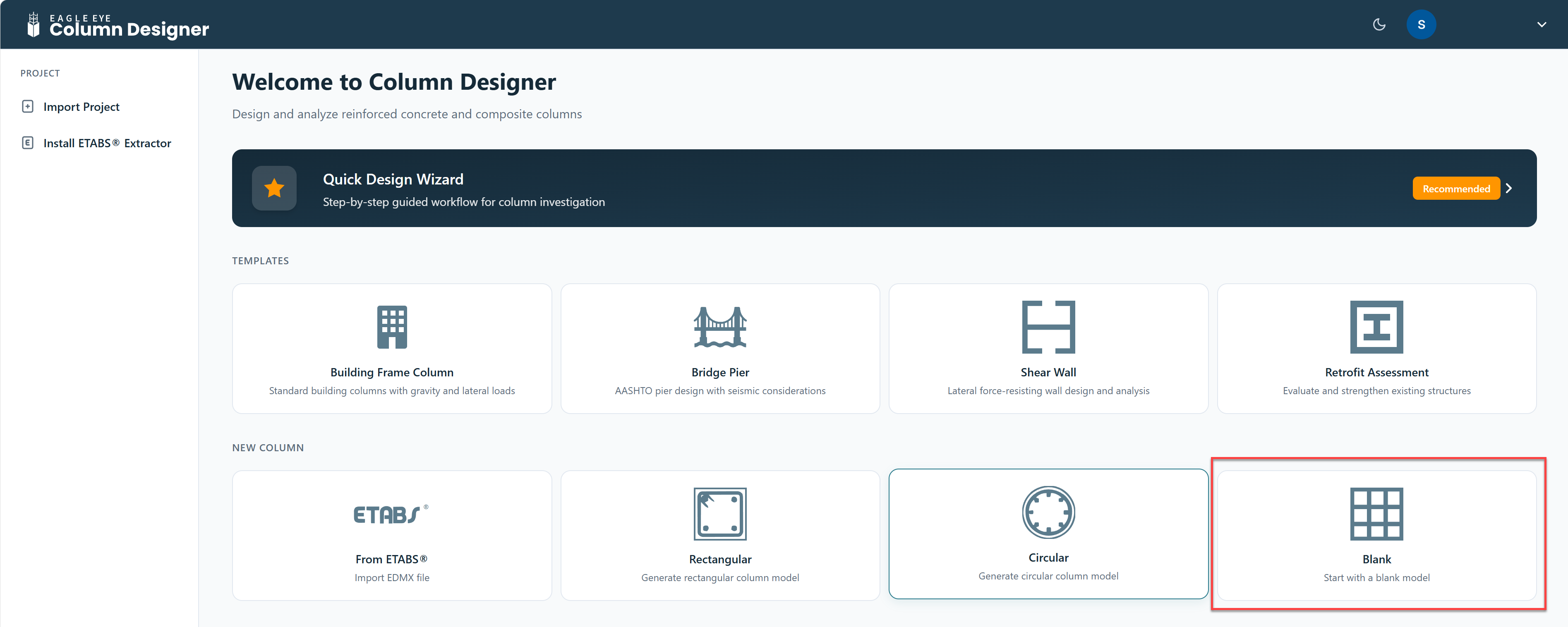
Figure: Blank Model option in Column Designer
After creating a blank working area, add shapes using the Draw Menu tools, then follow the same workflow from Step 2 onward (define materials, edit properties, set slenderness if needed, define loading, apply Auto Design, and review results).
Importing from ETABS
The Import ETABS Model feature allows direct import of concrete columns from an existing ETABS model, including loading conditions, material assignments, and framing conditions.
Step 1: Select ETABS File: Click Import ETABS Model. Browse to the ETABS model file and click Open.
Step 2: Select Stories and Load Combinations: Choose the stories and load cases/combinations to be imported.
Step 3: Select Columns: Use the 3D ETABS model viewer to visually select the columns to import. Multiple columns can be selected simultaneously.
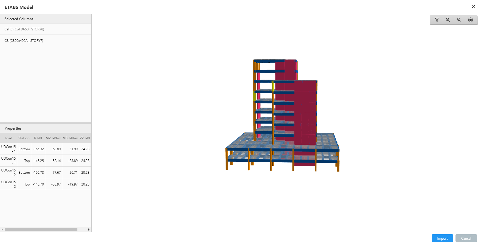
Figure: Importing columns from ETABS model
Step 4: Review Imported Columns: Imported columns appear under Project Explorer > Columns. For 10+ columns, use Define Menu > Project > Columns for a tabular view.
Notes on ETABS Import ETABS must be installed on the computer for this feature to work. Effective Length Factors (K) are NOT imported and must be defined manually. Working units in Column Designer match the ETABS database units (US inch or SI mm). MKS models are automatically converted to SI. If a design code used in ETABS is unavailable in Column Designer, the model opens using ACI 318-19 by default. Clear cover in Column Designer is measured to the outer edge of the main bar. The tie diameter is added to the imported cover value automatically. |
|---|
Cross-Section Modeling
Adding Shapes
Shapes are the basic building blocks of column sections. The following tools are available under Draw Menu:
- Draw Menu > Concrete Shapes: Draw basic concrete shapes (Rectangle, Box, Circle, Tee, Pipe, Channel, Angle, Polygon) in the working area.
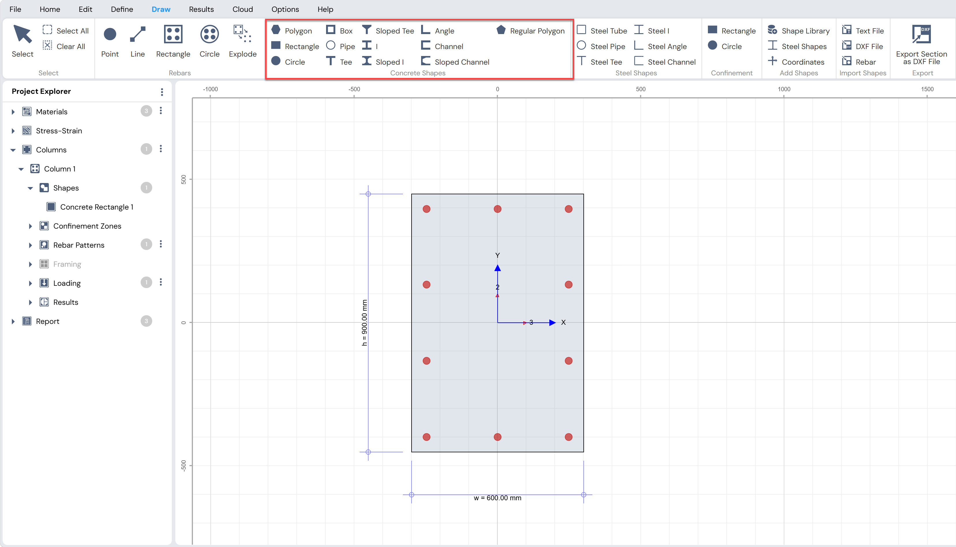
Figure: Adding basic concrete shapes from Draw Menu
- Draw Menu > Add Shapes > Shape Library: Select from predefined shape libraries including AISC, BS, CISC steel shapes, Bridge Pier shapes, Shear Walls, and others.
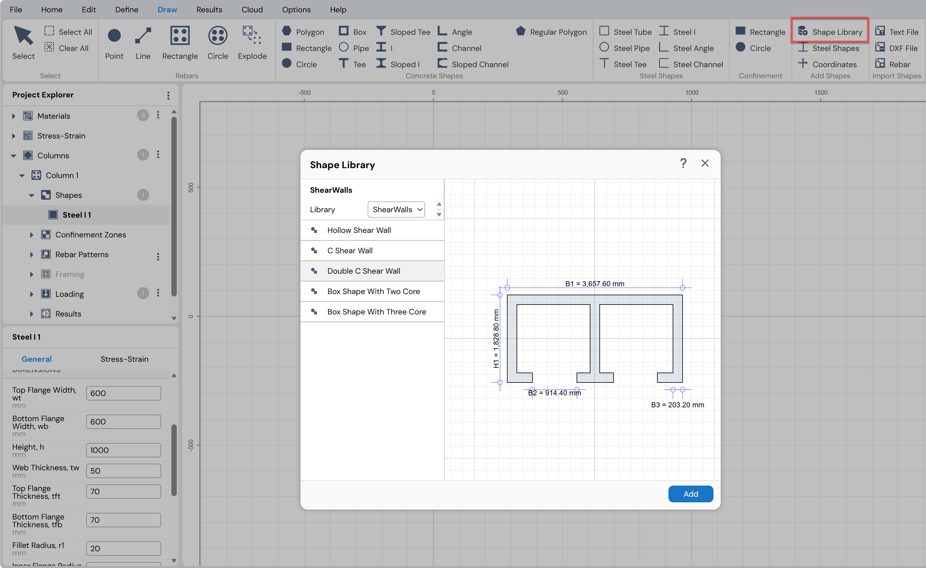
Figure: Adding shapes from Shape Library
Draw Menu > Add Shapes > Coordinates: Enter nodal point coordinates manually or import from a text file.
Draw Menu > Import Shapes > DXF File: Import custom shapes drawn in AutoCAD.
Adding Reinforcement
Rebar can be placed anywhere within the cross-section using patterns available under Draw Menu > Rebars:
Point: Place a single rebar at a specified location.
Line: Draw a line of rebars along a specified direction.
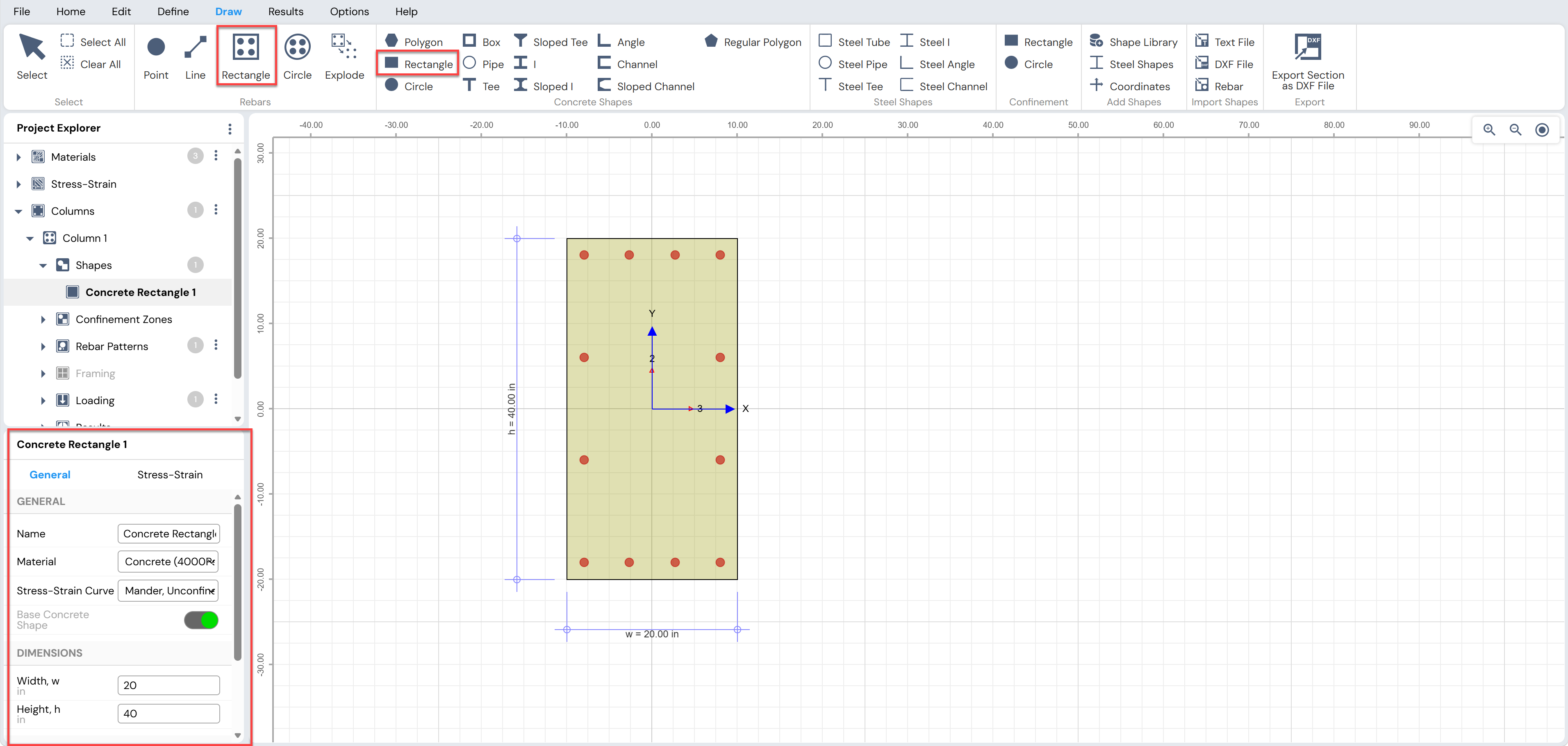
Rectangle: Draw rebars arranged in a rectangular pattern.
Circle: Draw rebars arranged in a circular pattern.
Import Rebar: Import rebar data from a CSV file (Draw Menu > Import Shapes > Rebar). Format: x-coordinate, y-coordinate, rebar diameter.
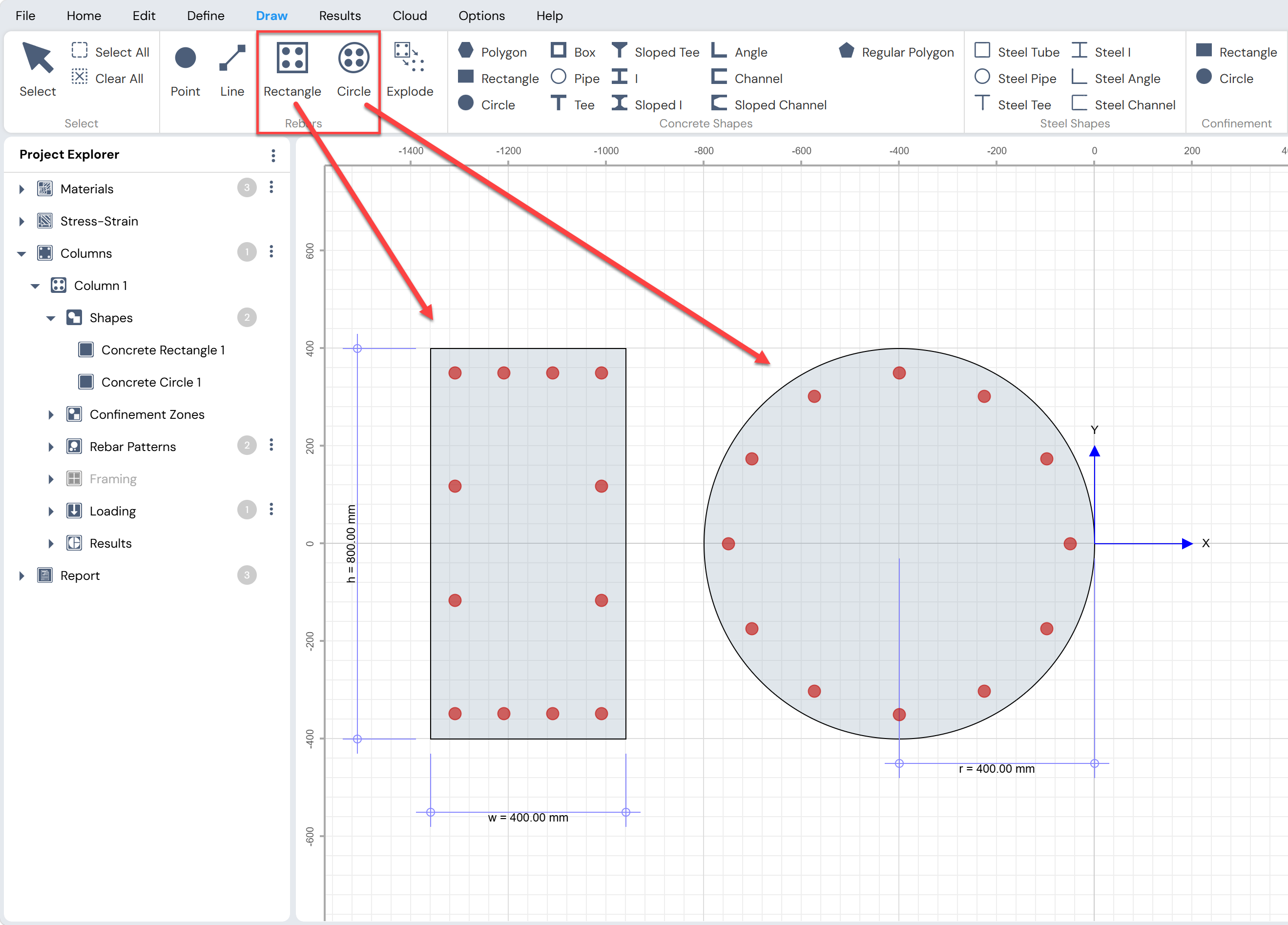
Figure: Rectangular and Circular rebar pattern options
After placement, click on a rebar pattern to activate the Property Grid and edit the number of bars, clear cover, and minimum clear spacing. Note: clear cover in Column Designer is measured to the outer edge of the main bar.
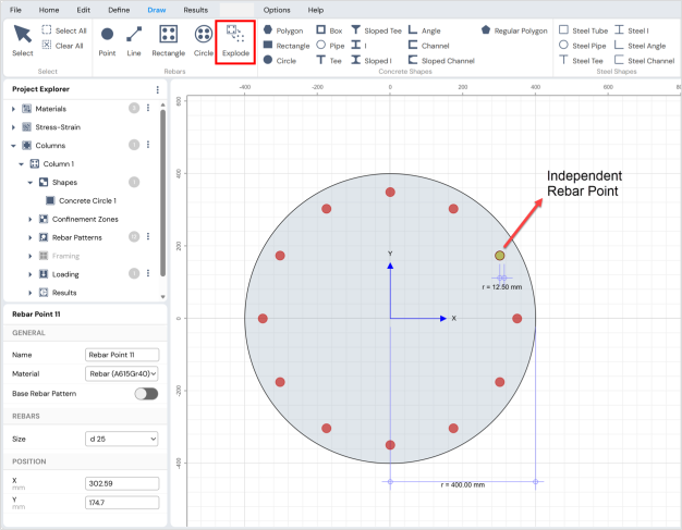
Figure: Explode Rebar Patterns to convert patterns into individual points
Editing Shapes
Shapes can be modified after placement using tools available under Edit Menu:
Flip: Mirror a shape horizontally or vertically.
Merge: Combine multiple shapes into a single composite shape.
Stack: Arrange shapes vertically.
Align: Align shapes relative to each other or the working area.
Move Sections: Reposition shapes precisely.
Edit Points: Modify nodal coordinates for polygon shapes.
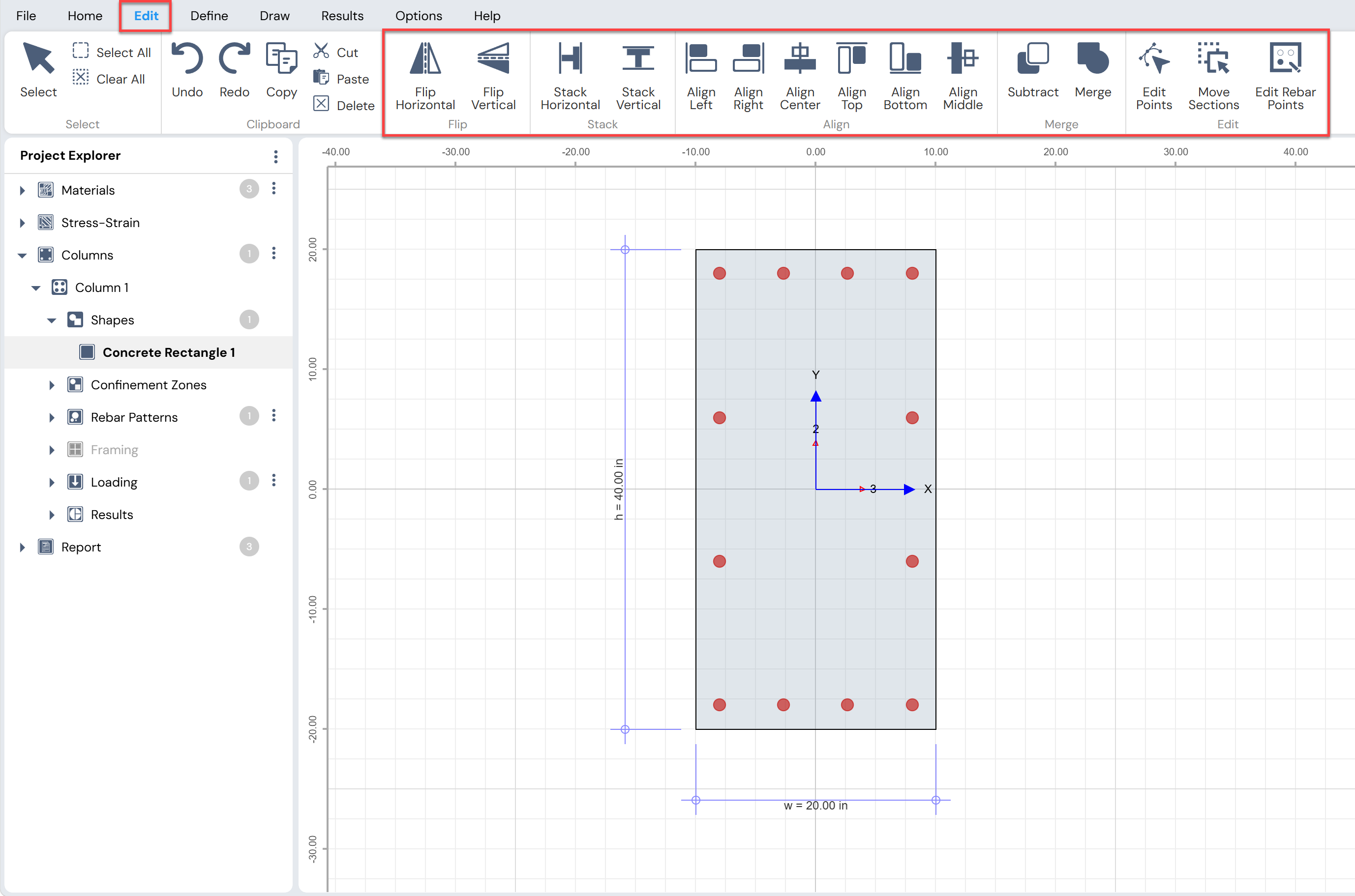
Figure: Editing and modifying shapes in Column Designer
Composite Columns
Composite columns are created by placing shapes made of different materials over each other. Column Designer automatically accounts for overlapping areas when computing section properties. Concrete is treated as the base material and transformed section properties are reported. No manual hole creation is needed before overlapping shapes.
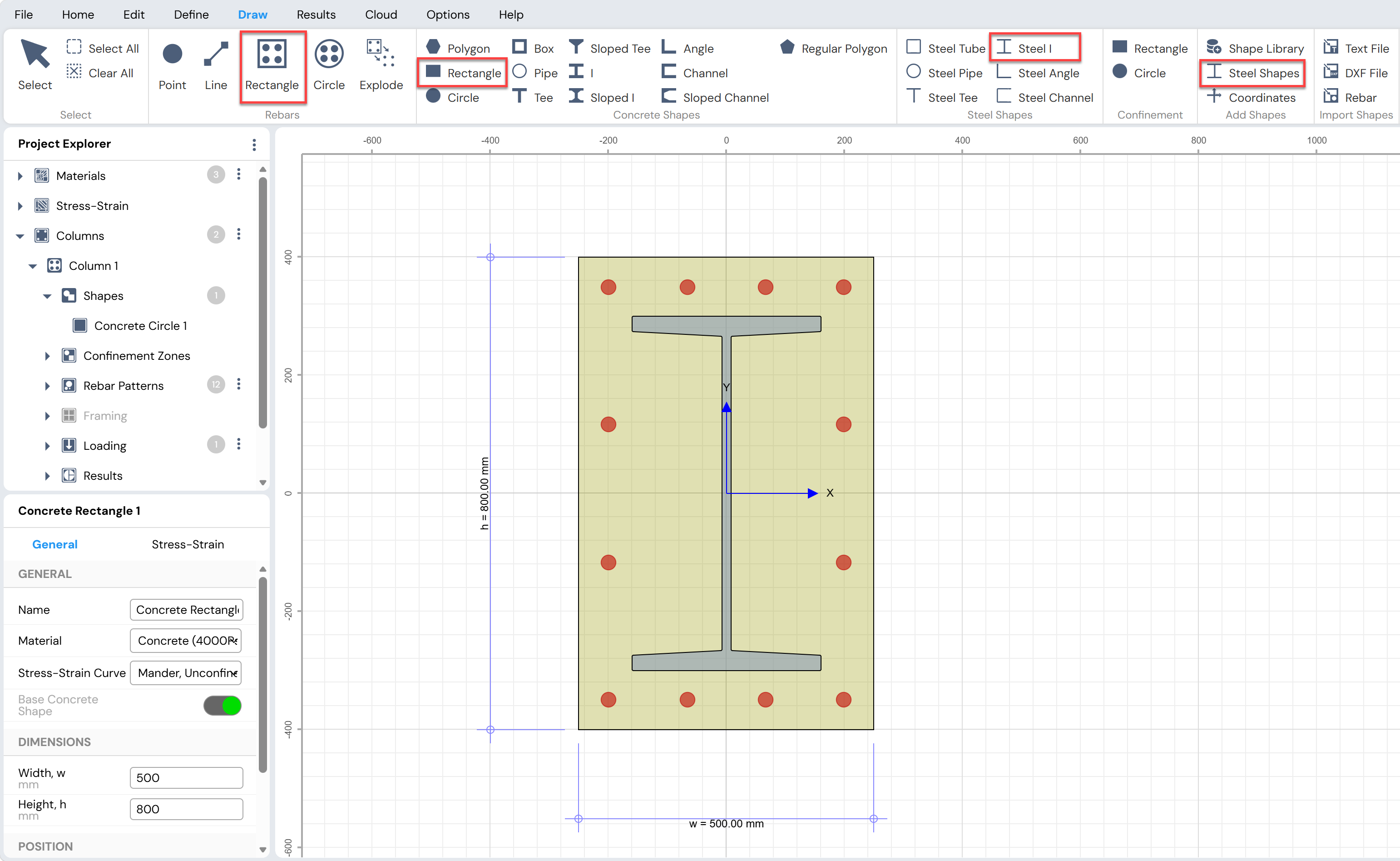
Figure: Creating Composite Column in Column Designer
Defining Materials and Stress-Strain Models
Material and constitutive model definitions are managed via:
Materials: Define Menu > Project > Materials. View, modify, or add materials using the Material Library.
Concrete Stress-Strain and Confinement: Define Menu > Stress Strain > Concrete. Default: Mander’s Unconfined model. Assign to shapes via Property Grid > Stress-Strain Curve.
Steel Stress-Strain: Define Menu > Stress Strain > Steel. Default: Park Strain Hardening. Assigned at the material level, not per individual rebar.
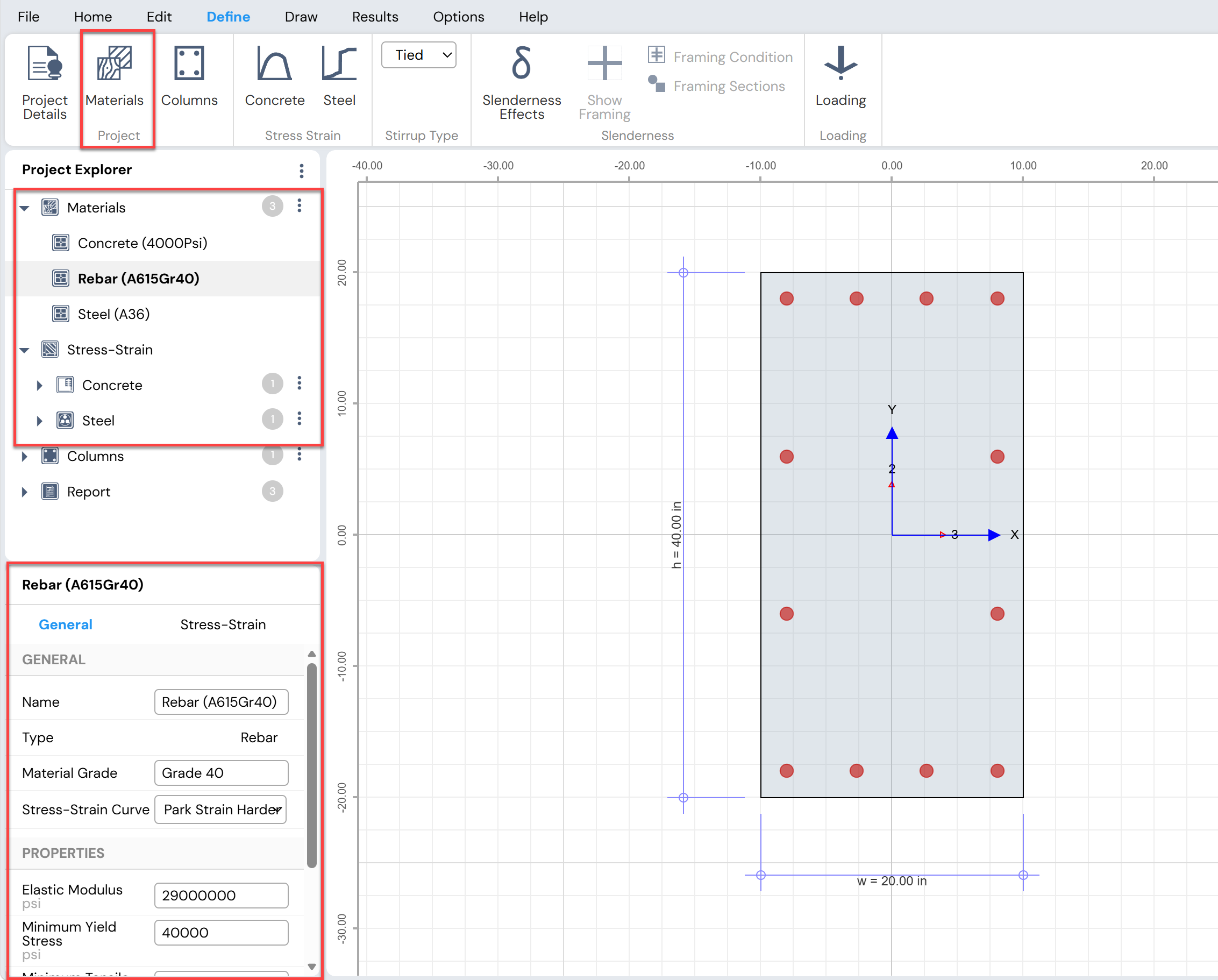
Important Note Stress-strain and confinement models are used ONLY for moment-curvature analysis. They do NOT affect P-M capacity calculations, which use the material properties defined under Define > Materials. |
|---|
Considering Slenderness Effects
Column Designer provides comprehensive tools to evaluate slenderness effects and calculate magnified design moments for both sway and non-sway conditions, in accordance with the selected design code.
Enabling Slenderness
Navigate to Define Menu > Slenderness > Slenderness Effects and toggle it on. Once enabled, framing conditions must be defined. If slenderness is disabled, the program treats the column as short and ignores magnified moments.
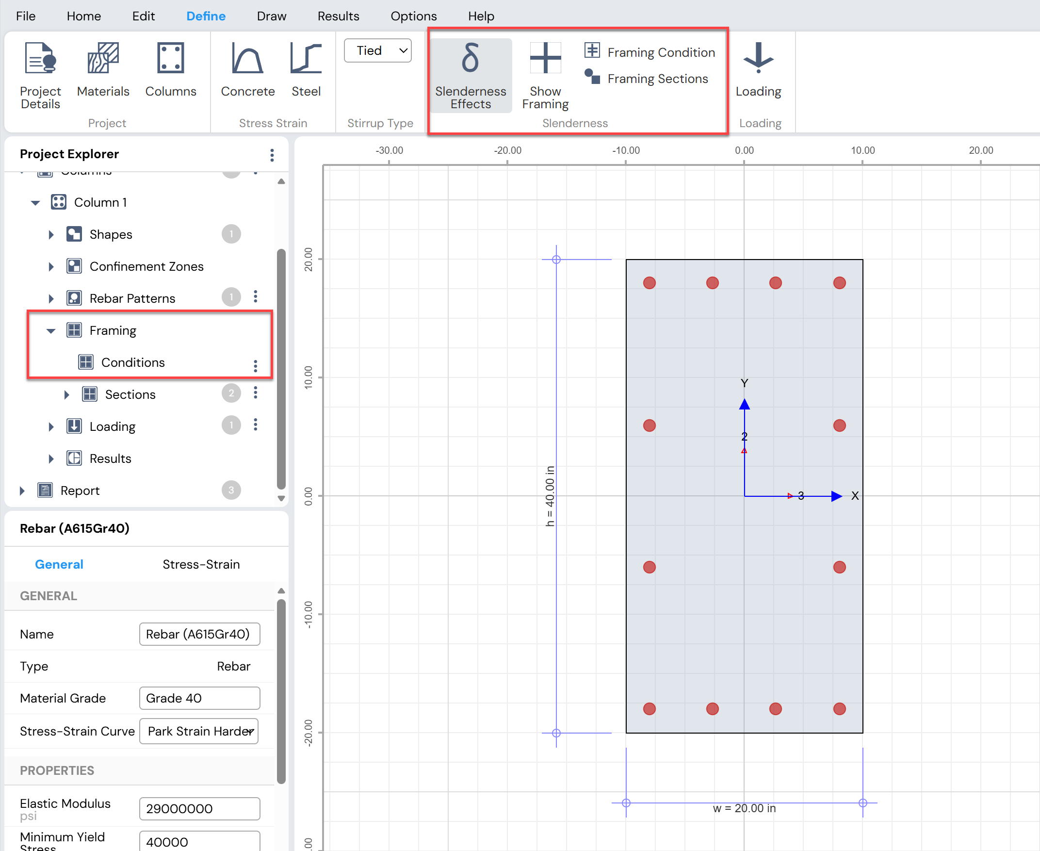
Figure: Slenderness option in Define Menu and Project Explorer
Defining Framing Conditions
Access framing conditions via Define Menu > Slenderness > Framing Conditions, or Project Explorer > Columns > Framing > Conditions. Column Designer uses these conditions to automatically determine the Effective Length Factor (K) based on end restraints, column height, and code-specified criteria.
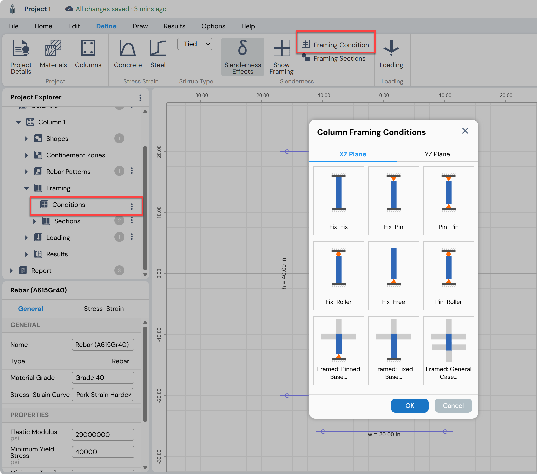
Figure: Framing Conditions for slender columns
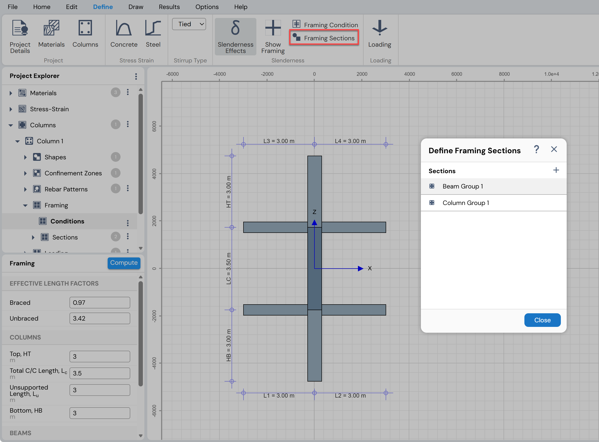
Figure: Defining Framing Sections
Loads for Slender Columns
For slender columns, Detailed Loading Mode is required (Define Menu > Loading > Loading). This mode allows definition of sway and non-sway load components separately. Magnified moments are computed automatically and can be reviewed from Results Menu > Capacity > Design Loads.
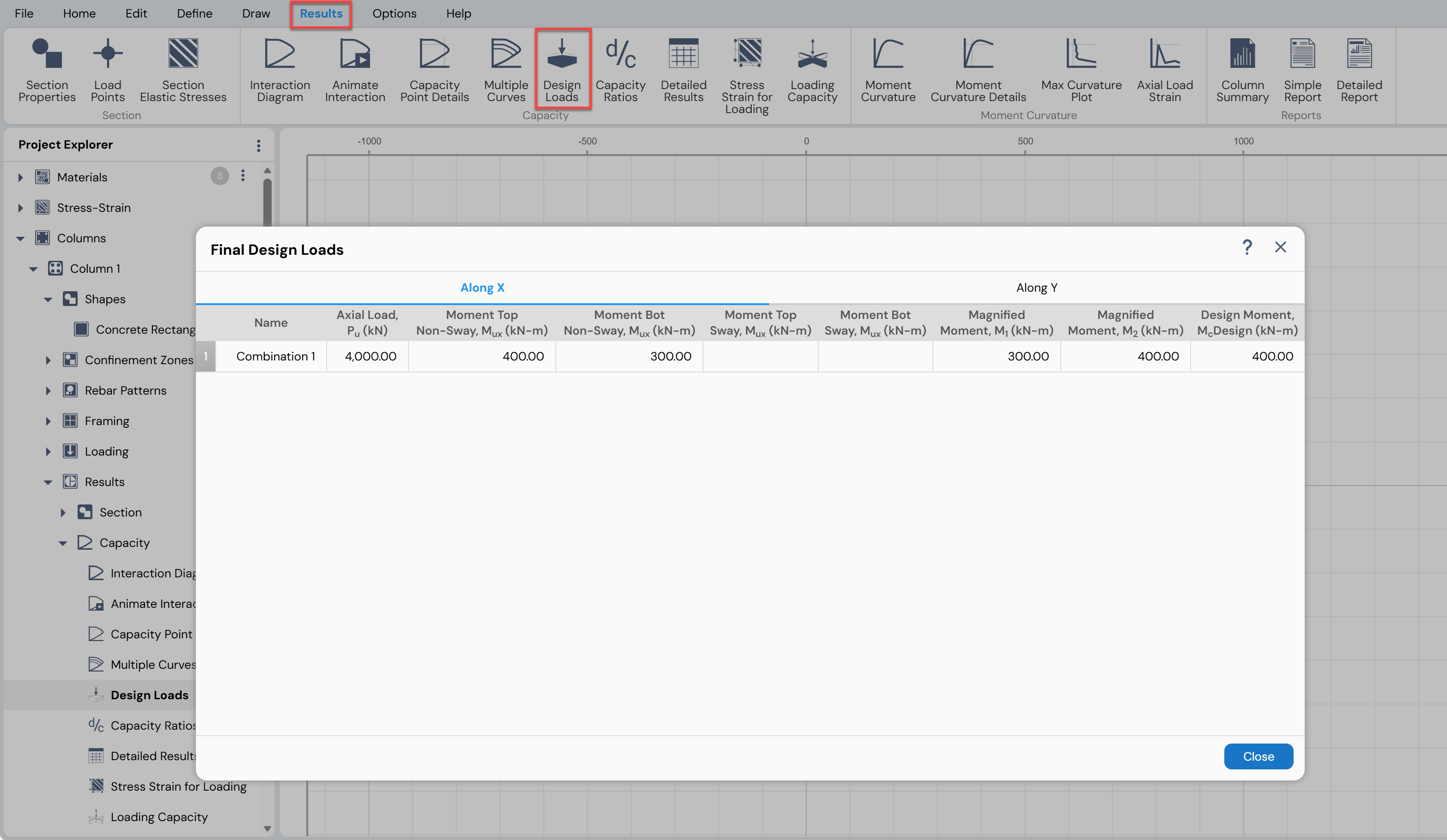
Figure: Viewing Final Design Loads (magnified moments)
Specifying Column Loads
Column loads are defined via Define Menu > Loading > Loading or Project Explorer > Columns > Loading. Two loading modes are available:
Simple Loading Mode (Short Columns)
Used when slenderness effects are not considered. Allows direct entry of factored axial loads and moments for each load combination.
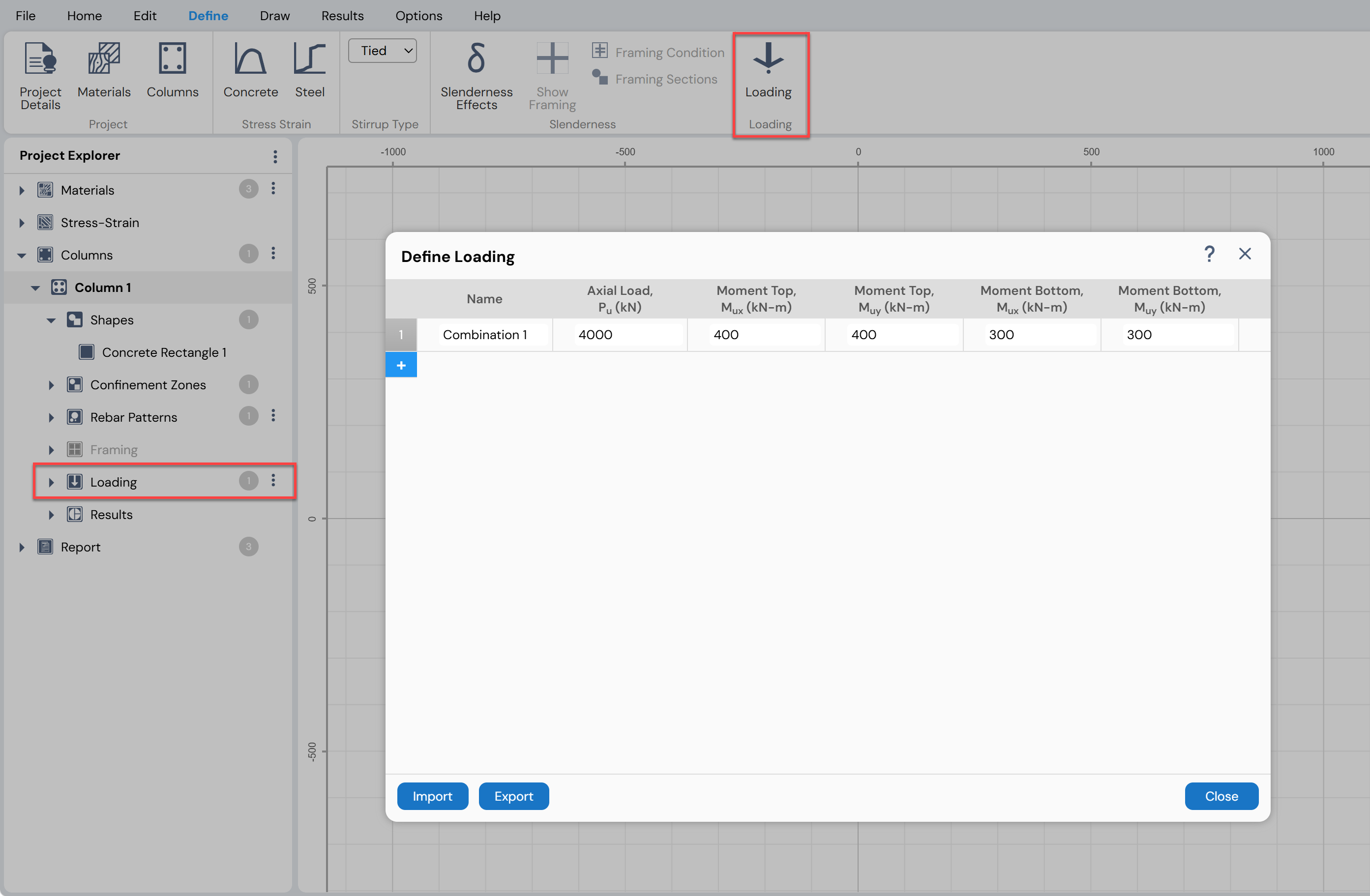
Figure: Defining Simple Load Combinations for columns
Detailed Loading Mode (Slender Columns)
Required for slender columns. Allows specification of top and bottom moments per load combination, sway and non-sway load components, and the sustained axial load ratio for effective stiffness calculations. Column Designer then calculates magnified moments in accordance with the selected design code.
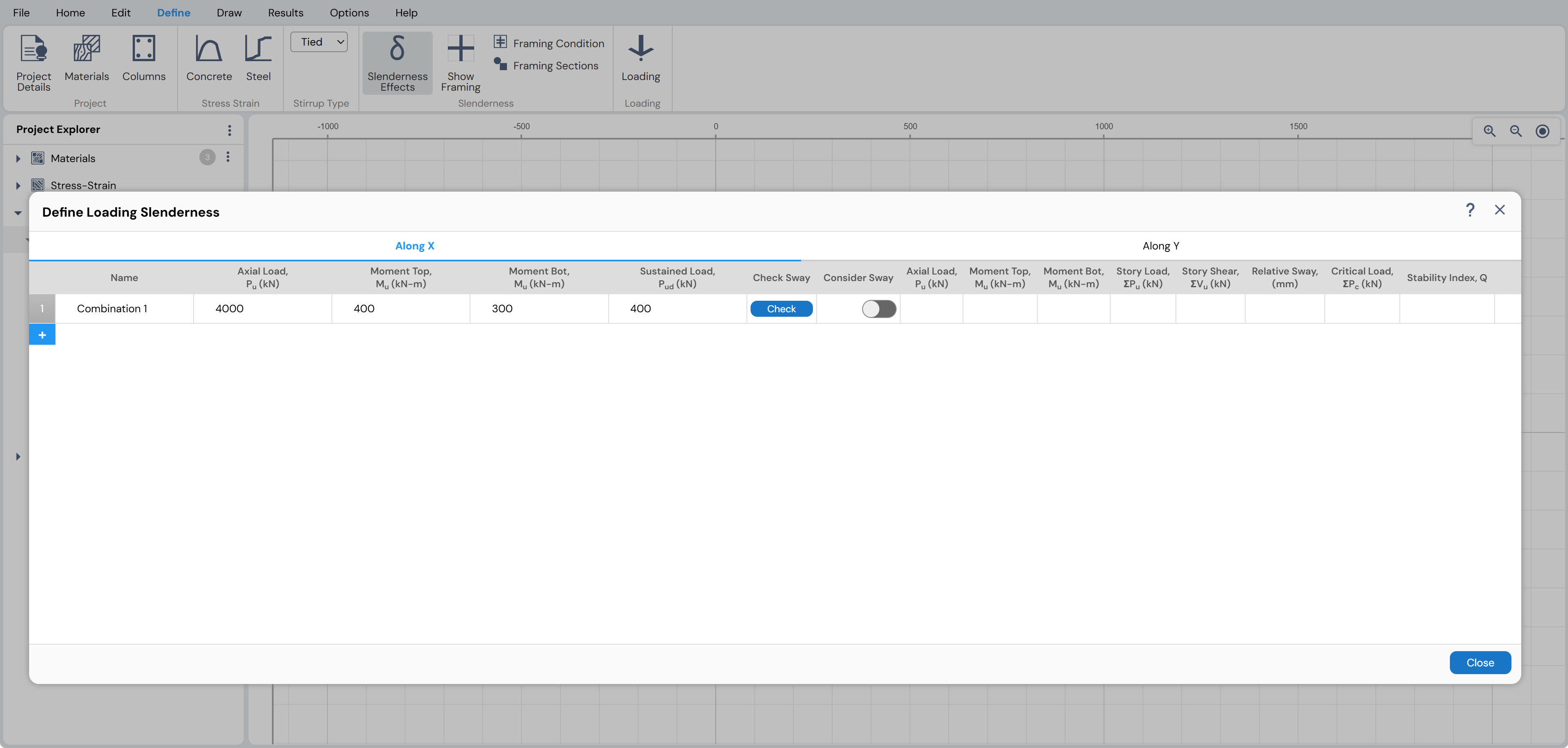
Figure: Defining Loading for slender columns
Obtaining Analysis and Design Results
Once a column section, materials, and loads are defined, results are accessed from Results Menu or Project Explorer > Columns > Results.
Section Properties
Displays computed cross-sectional properties including area, moments of inertia, shear areas, torsional constant, radii of gyration, section moduli, and reinforcement ratio. For composite sections, transformed section properties are reported.
Interaction Diagrams and Capacity
Column Designer generates three types of interaction results:
Interaction Surface: A 3D color-coded plot showing the variation of axial load (P), major moment (M2), and minor moment (M3).
P-M Curve: Load-moment interaction curve for a specified neutral axis angle, showing axial capacity, resultant moment capacity, forces in concrete/reinforcement, strain distribution, and neutral axis depth.
M-M Curve: Moment-moment interaction curve for a specified axial load level.
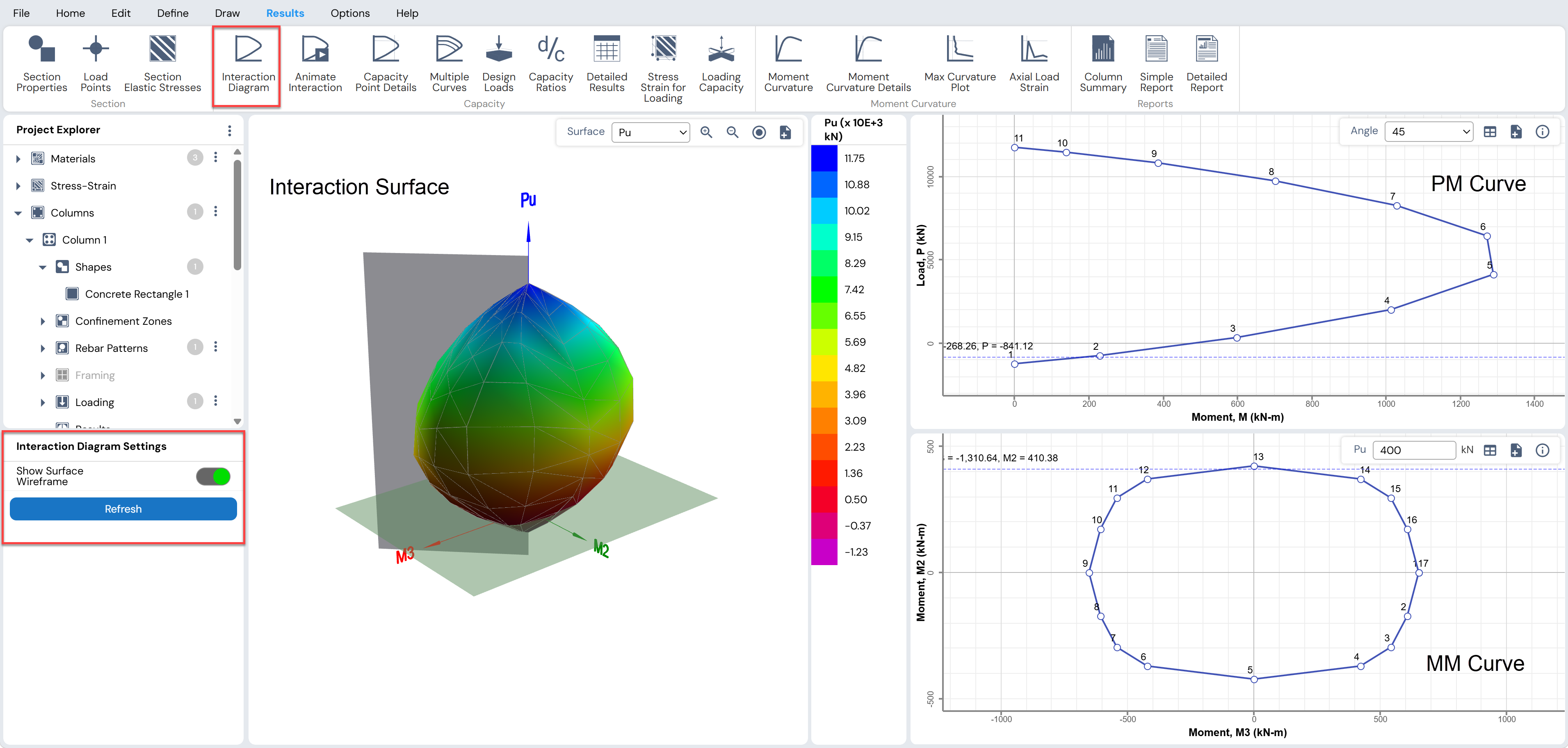
Figure: Interaction Diagram Screen
Multiple P-M or M-M curves can be plotted on the same graph by varying concrete strength (fc’), steel yield strength (fy), or reinforcement sizes, enabling comparative parametric studies.
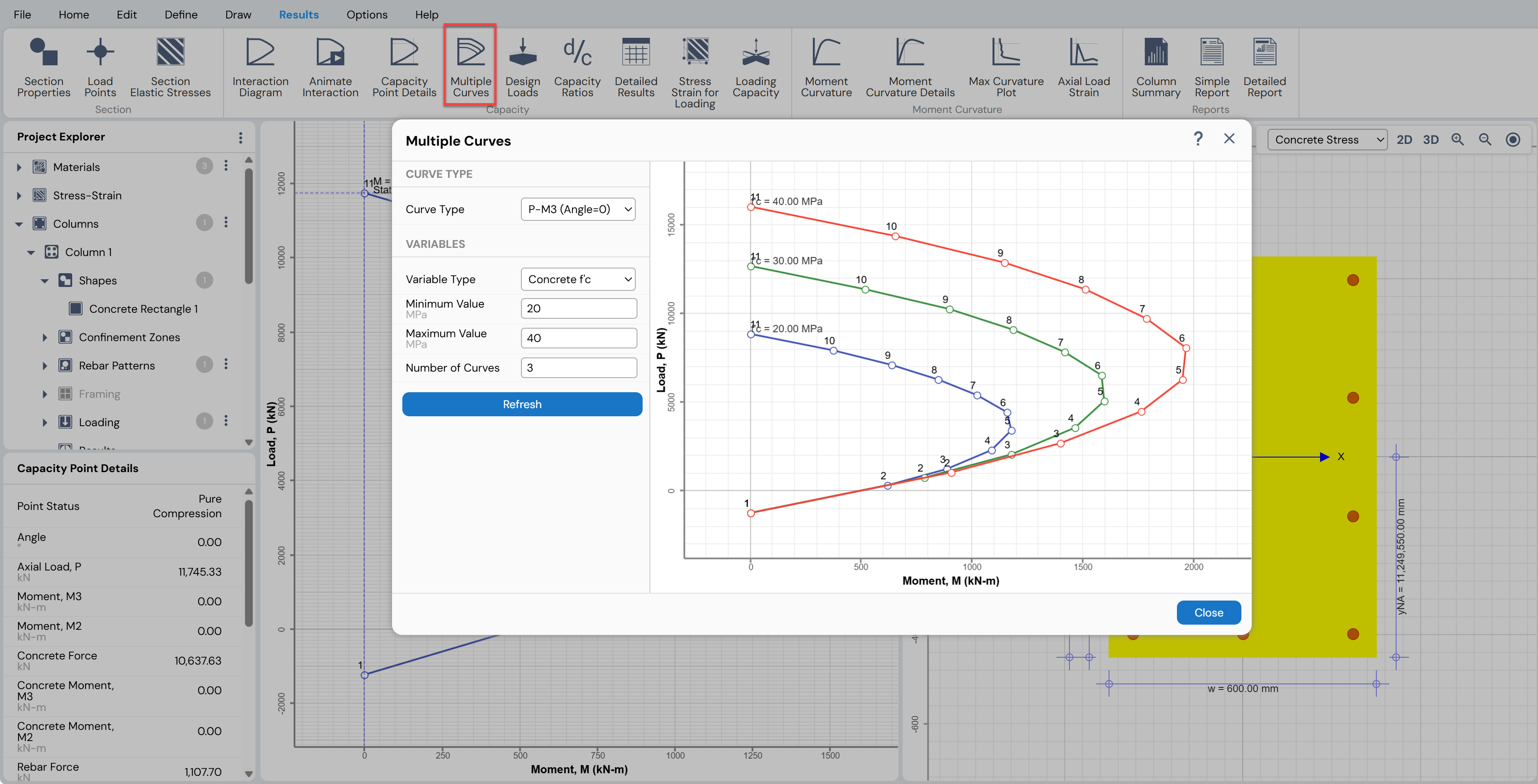
Figure: Multiple Curves feature in Column Designer
Capacity Ratio Check
Capacity ratios are computed using three methods: Moment Sum at P, Moment Vector at P, and Axial Capacity Ratio. A capacity ratio of 1.0 or less indicates an adequate section. The program also reports resultant moment angle and neutral axis depth.
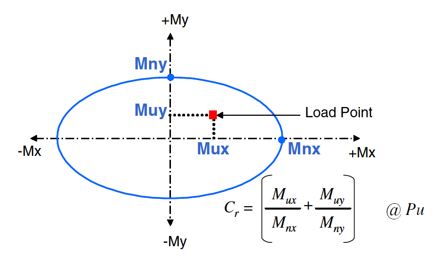
Figure: Capacity Ratio based on Moment Sum at P
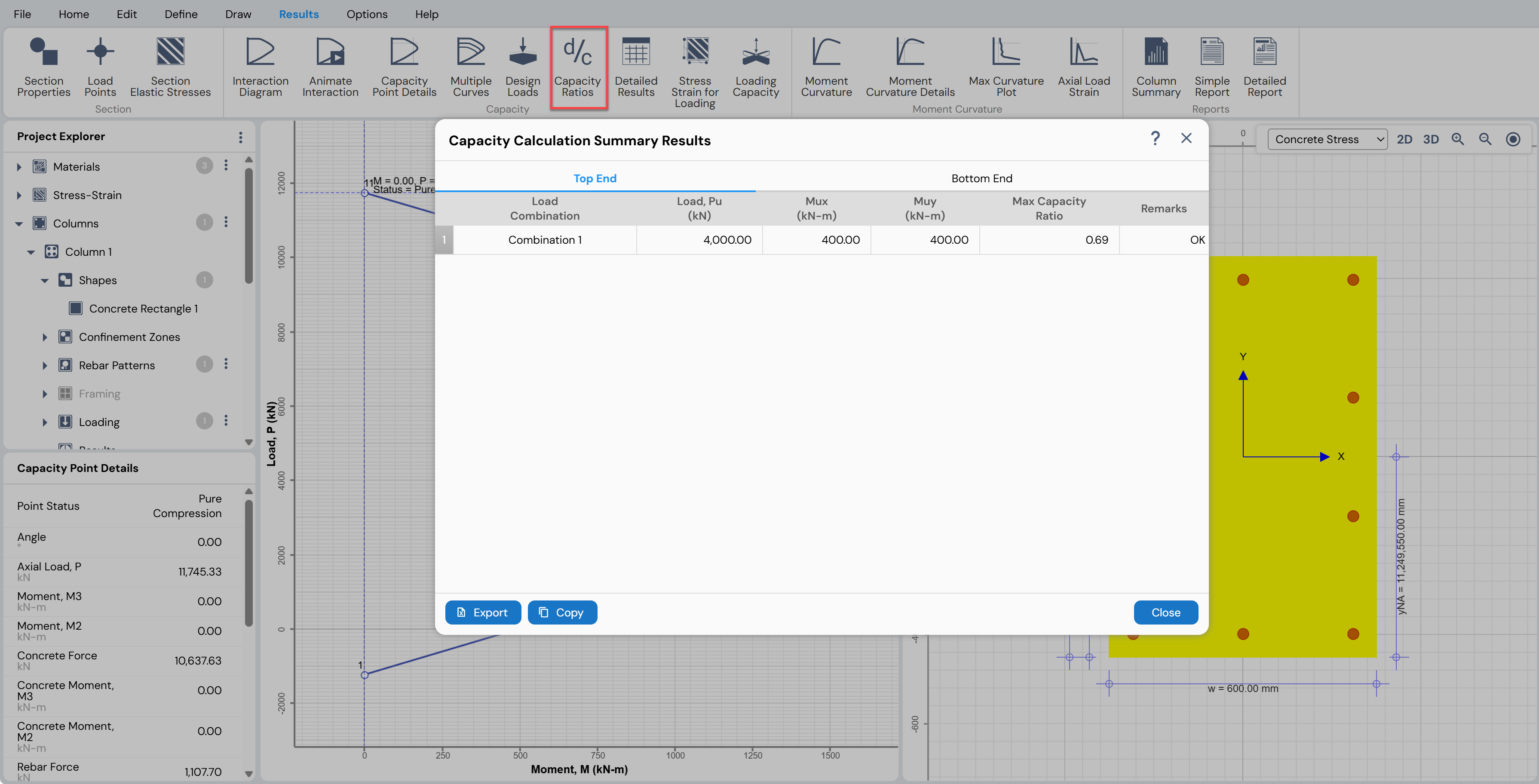
Figure: Capacity Calculation Results form
Stress Distribution
Flexural stress distribution can be displayed for a selected load combination as color-coded contours in 2D or 3D view.
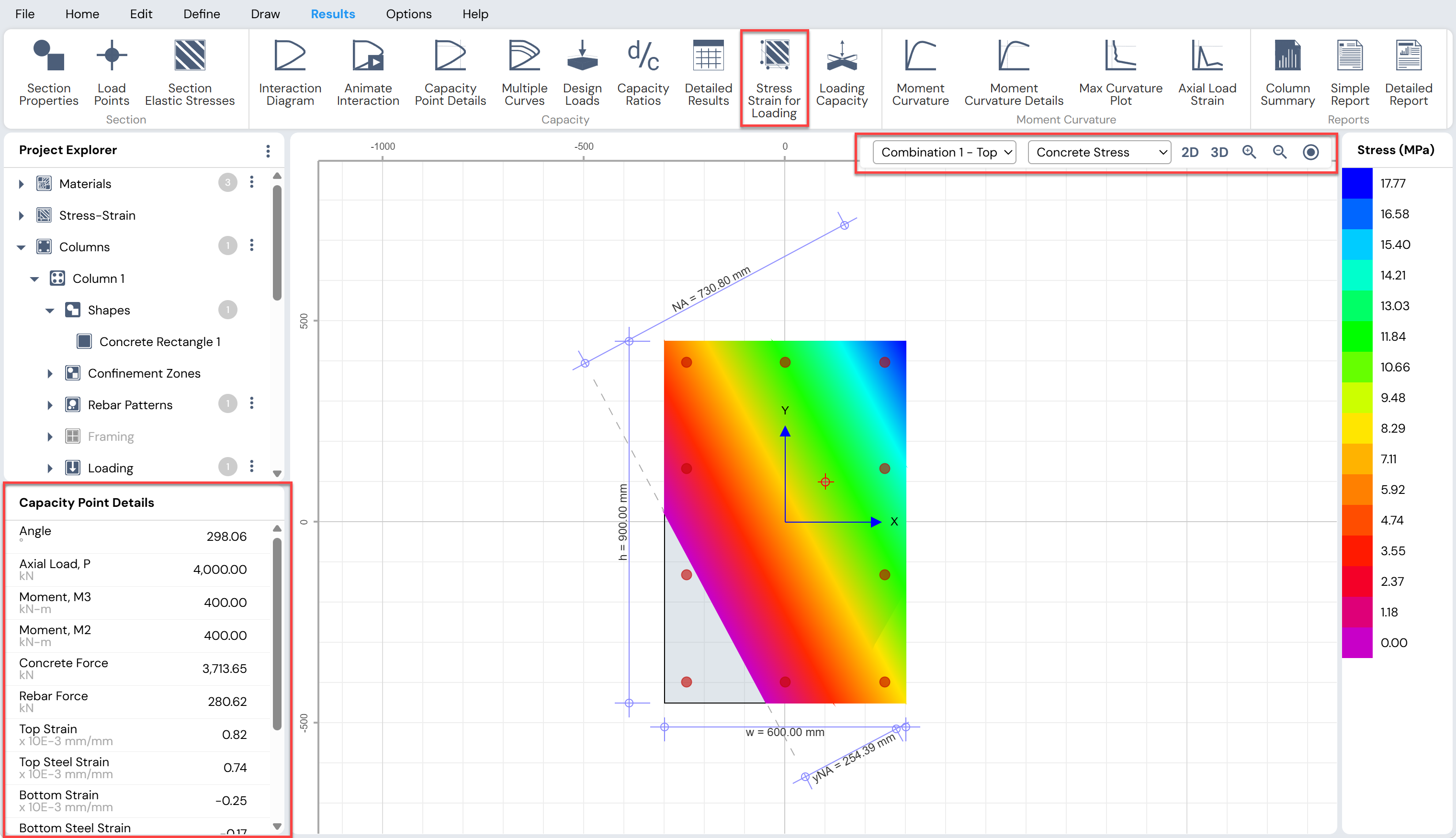
Figure: Stress-strain contours for given loading
Moment-Curvature Analysis
Moment-curvature curves are generated for a specified neutral axis orientation and axial load level, providing insight into section ductility and performance. Results are computed using the assigned stress-strain and confinement models.
Auto Design
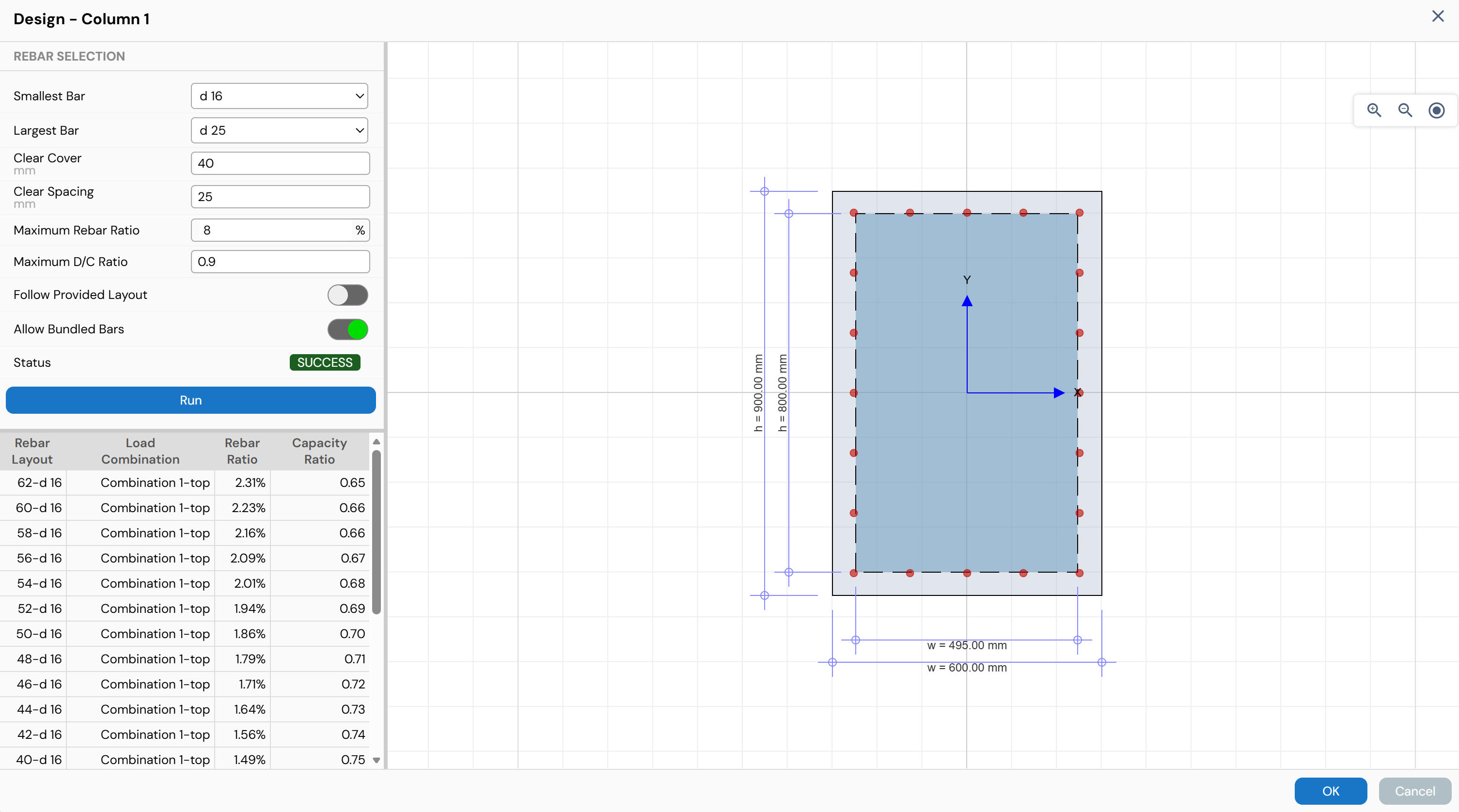
The Auto Design feature iteratively determines the optimum reinforcement layout. Access via Home Menu > Design > Auto-Design. Available only for rectangular and circular reinforced sections.
Design constraints that can be specified:
Maximum and minimum rebar size
Maximum allowable rebar ratio in the section
Clear cover and clear spacing limits
Maximum D/C ratio target
Generating Reports
Column Designer can generate several types of reports, accessible from Project Explorer > Report or Results Menu > Reports.
Report Types
| Report Type | Description |
|---|---|
| Column Summary | A summary table for all columns in the Project File, including governing load combination, reinforcement configuration, reinforcement ratio, and D/C ratio. |
| Simple Report (One-Page) | A one-page overview report for a selected column, suitable for a quick design summary. |
| Detailed Report | A comprehensive report covering all analysis inputs, section properties, interaction diagrams, and design results. Can be customized with user-added text and graphics. |
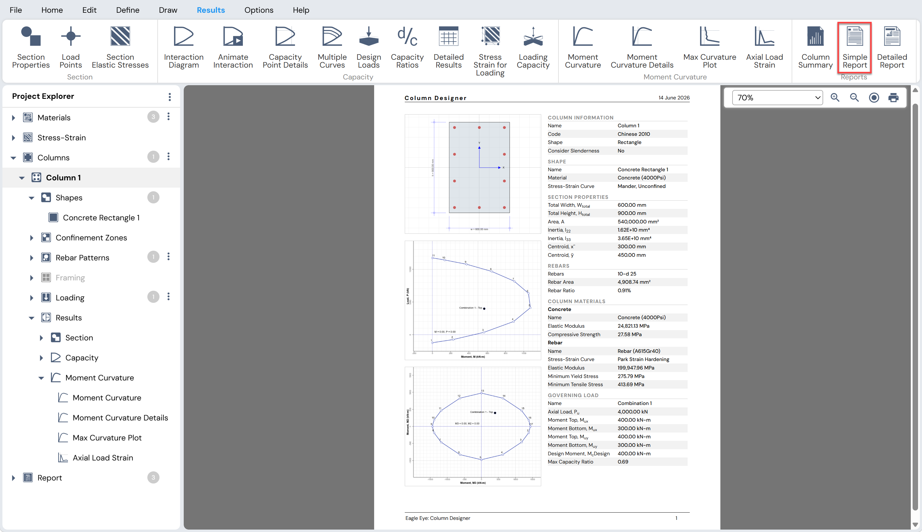
Figure: Simple One-Page Report view
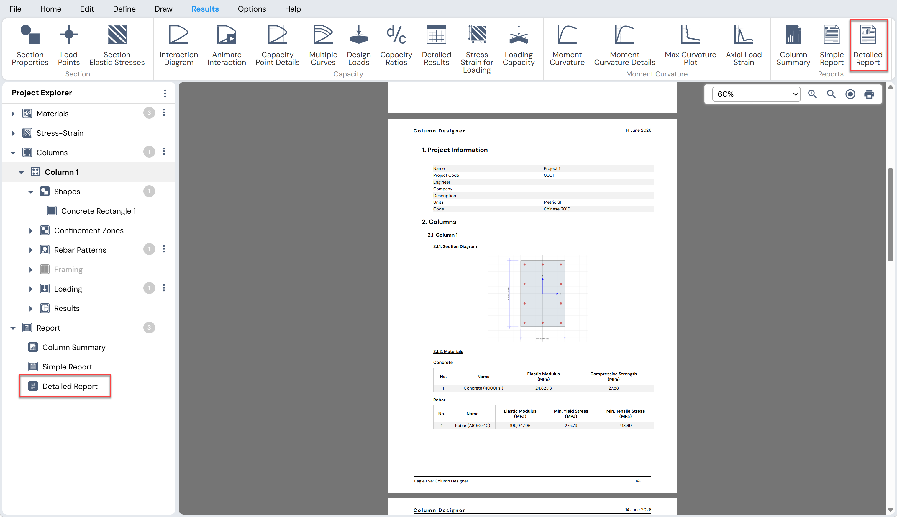
Figure: Detailed Report view
Customizing the Detailed Report
Add custom text sections
Include user-selected graphics such as interaction diagrams and stress contour plots
Select which result types to include in the report
Printing and Saving Reports
Reports can be printed directly or saved in standard file formats from the report viewer. Project information defined in Define Menu > Project > Project Details appears at the beginning of all detailed reports.