

Rectangular Column Design
Worked Example
1. Introduction and Problem Description
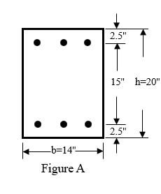
The short tied rectangular column shown in Figure A has cross-sectional dimensions of 14 in. × 20 in. and is subjected to the following design loads: P𝑢 = 374 kip and M𝑢 = 234 kip-ft. Given material properties of f′𝑐 = 4,000 psi and f𝑦 = 60,000 psi, determine suitable reinforcement using Column Designer and evaluate the column’s capacity and interaction diagram.
Solution:
This example illustrates the design and analysis of a short tied rectangular reinforced concrete column subjected to combined axial load and uniaxial bending moment. In general, columns rarely carry pure axial load; bending moments are almost always present due to eccentricity, frame action, or lateral loads. Therefore, column strength must be evaluated using axial load–moment interaction principles as specified in ACI 318-19.
2. Column Modelling in Column Designer
Column Designer
Start the Column Designer program.
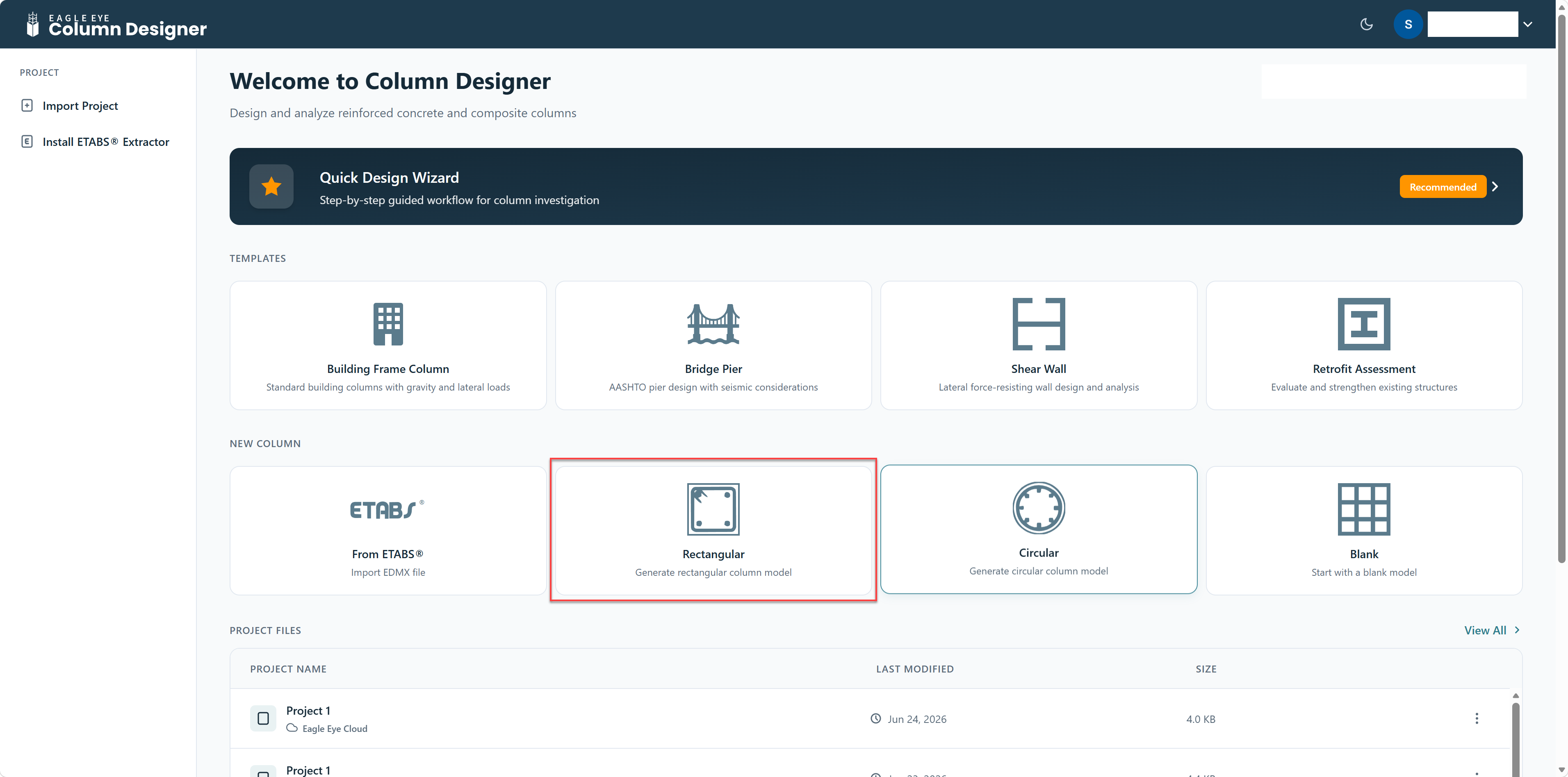
Upon launching the program, the start page presents several options for initiating a new project.
The available templates for new column include “Rectangular” for rectangular columns, “Circular” for circular columns, “Blank” for a custom cross-section, and “From ETABS” to import directly from an ETABS model.
For this problem, the rectangular column option is selected to model a column with a rectangular cross-section.
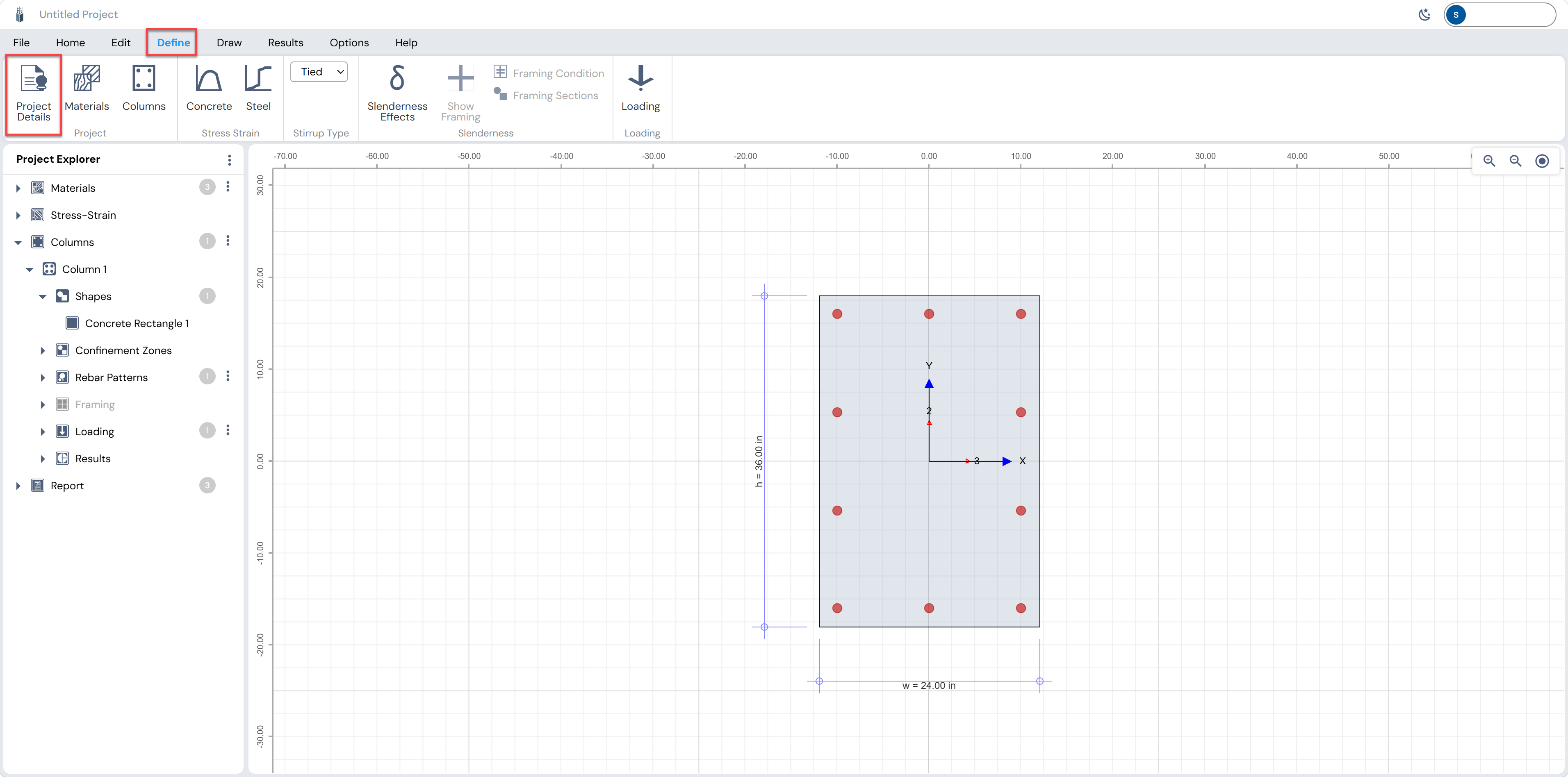
Begin by entering the project details.
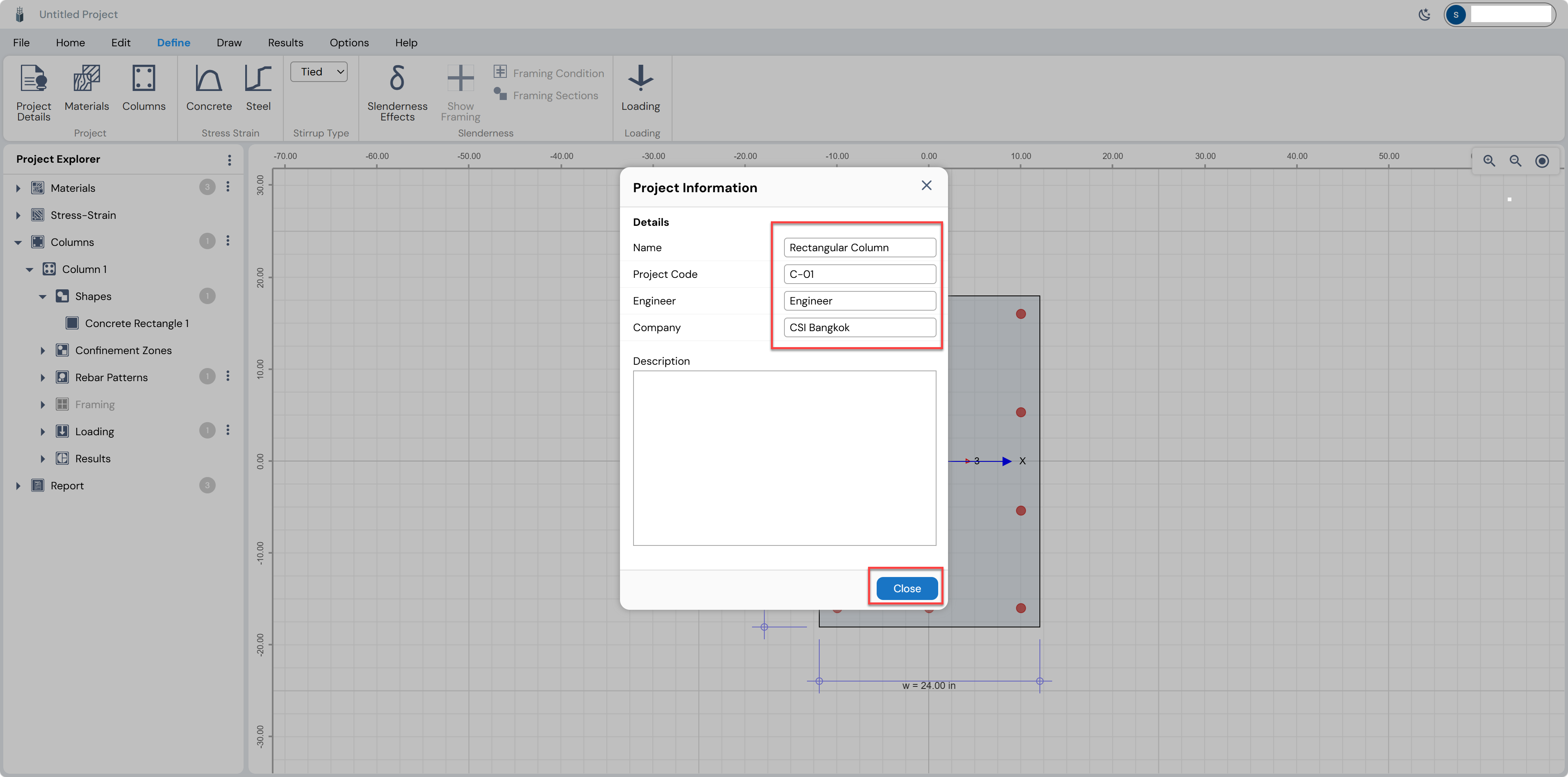
Click “Define” Tab. Then click “Project Details”.
The “Project Information” dialog box will appear.
This dialog allows entry of the project name, project code, engineer name, and company name.
A project description may also be entered in the provided field.
Then click “Close”.
Next, define the unit system for the project.
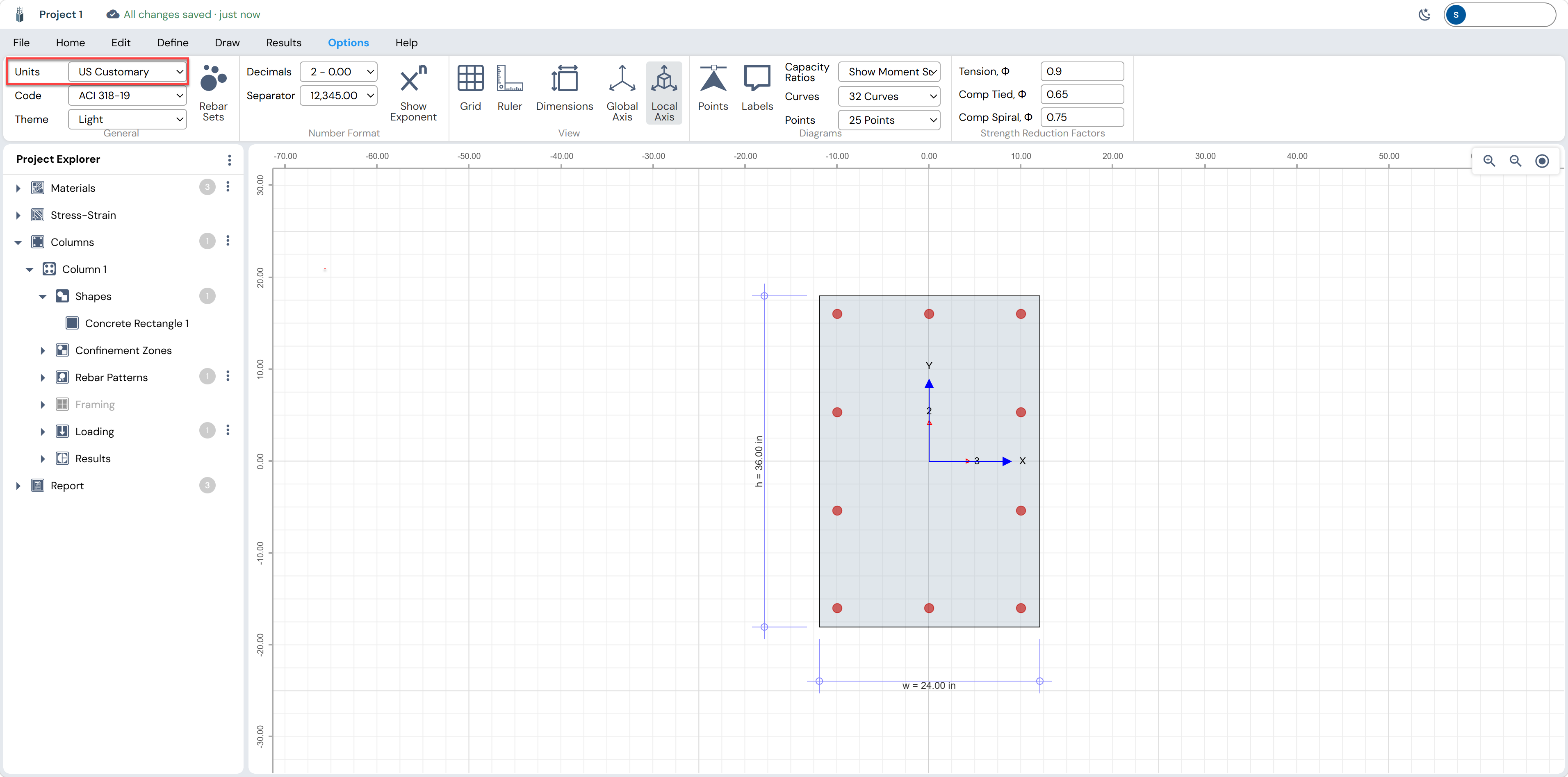
Click the “Options” tab.
Under the “Options” tab, select the desired unit system: “US Customary” for ft-in units, or “Metric SI” for mm or cm units.
For this example, inch units are used.
Set “Units” to “US Customary”.
Next, select the design code.
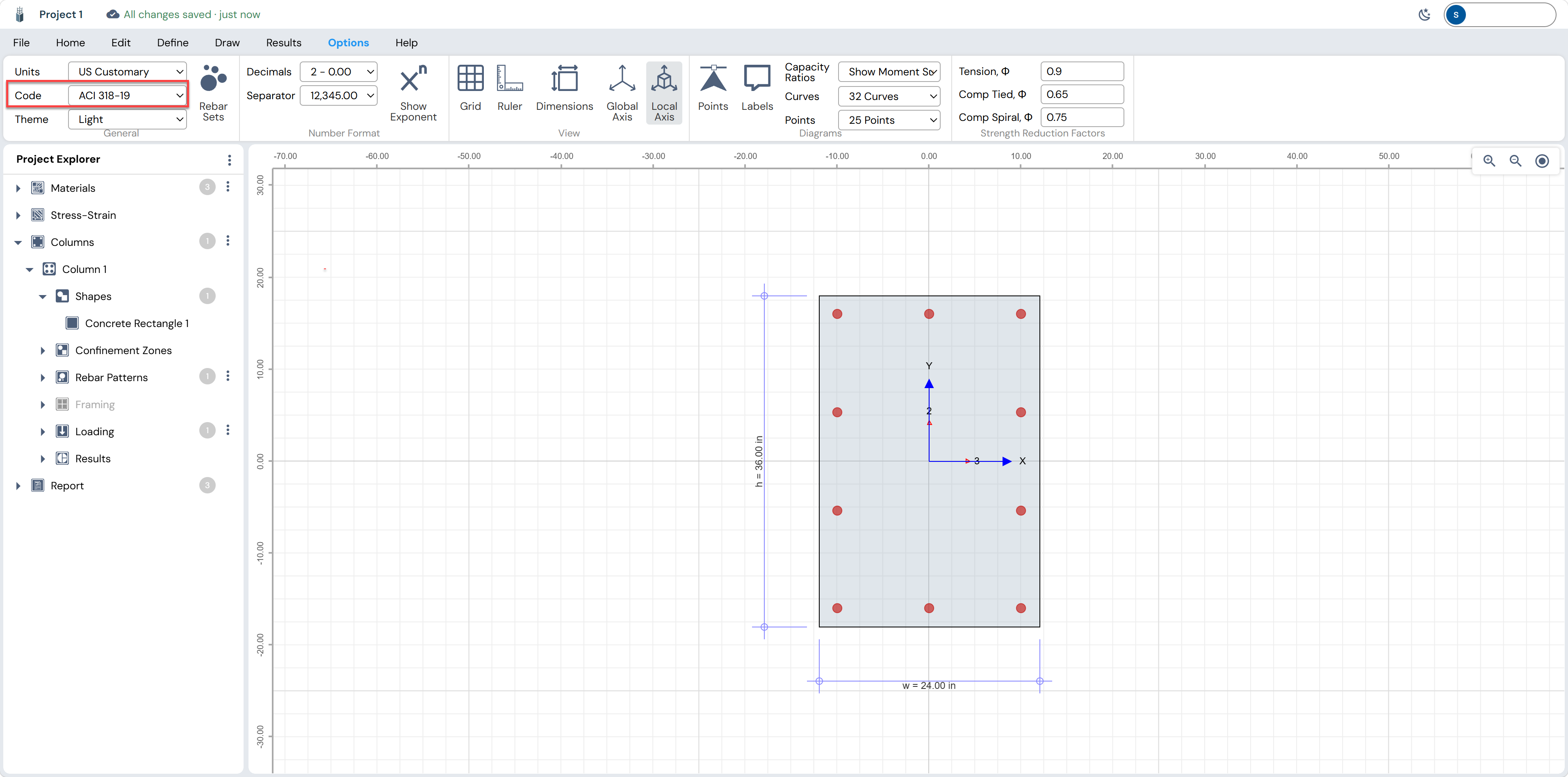
The program supports a range of international building codes, including ACI, BS, Eurocode, Chinese standards, and others.
For this example, set “Code” to “ACI 318-19”.
Next, define the material properties for concrete and reinforcing steel.
Click “Define” Tab and then click “Materials”.
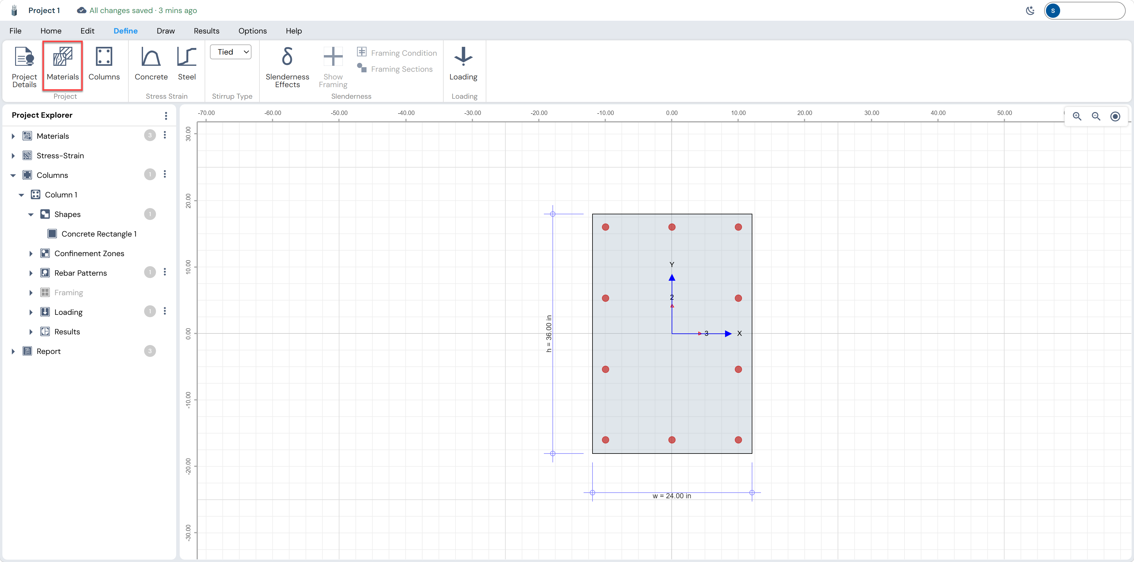
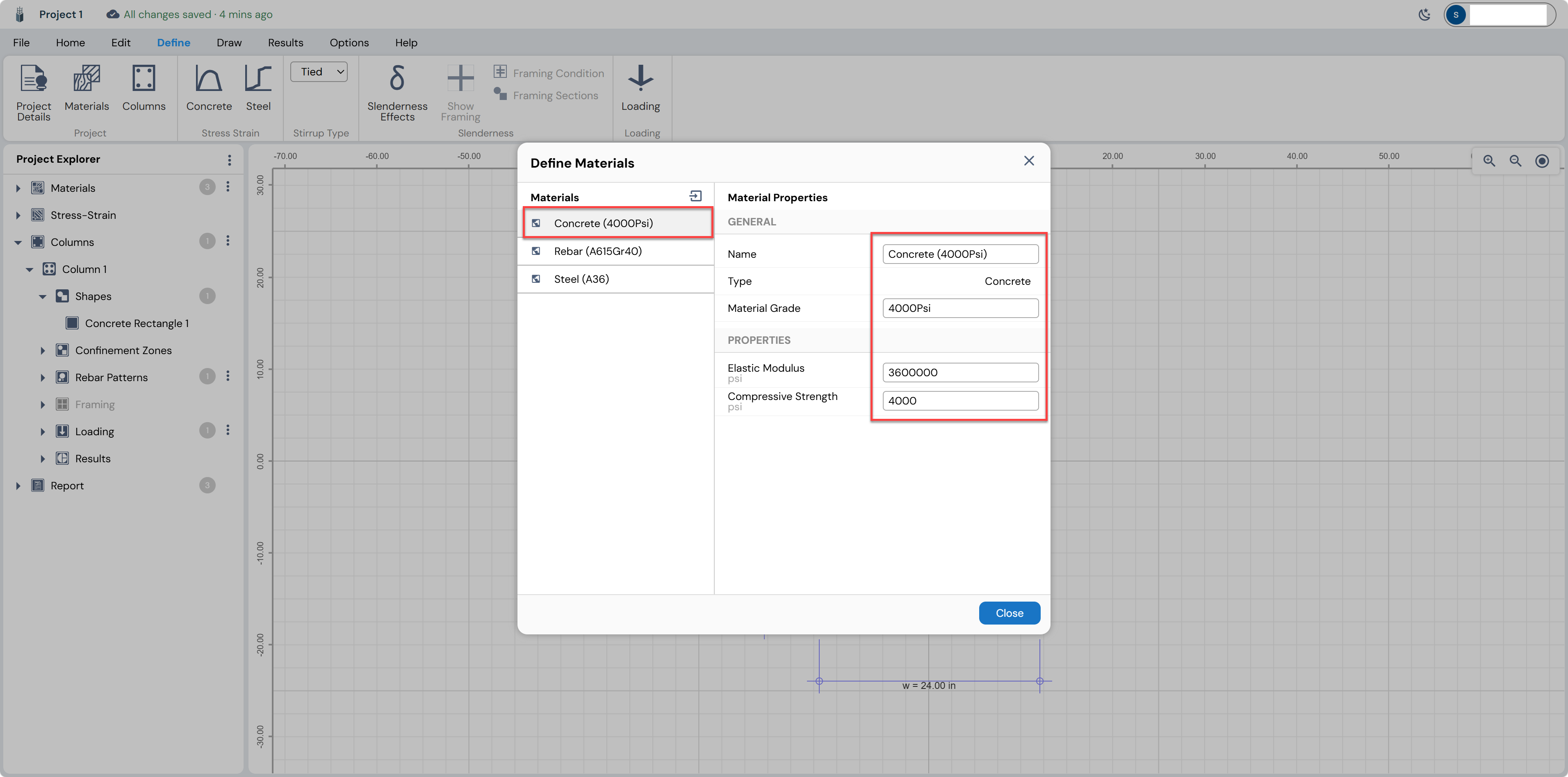
The “Define Materials” dialog box will appear.
In this dialog, define the concrete material properties first.
The required inputs include material grade, elastic modulus, and compressive strength.
For this example, enter f′𝑐 = 4,000 psi and E𝑐 = 3,600 ksi.
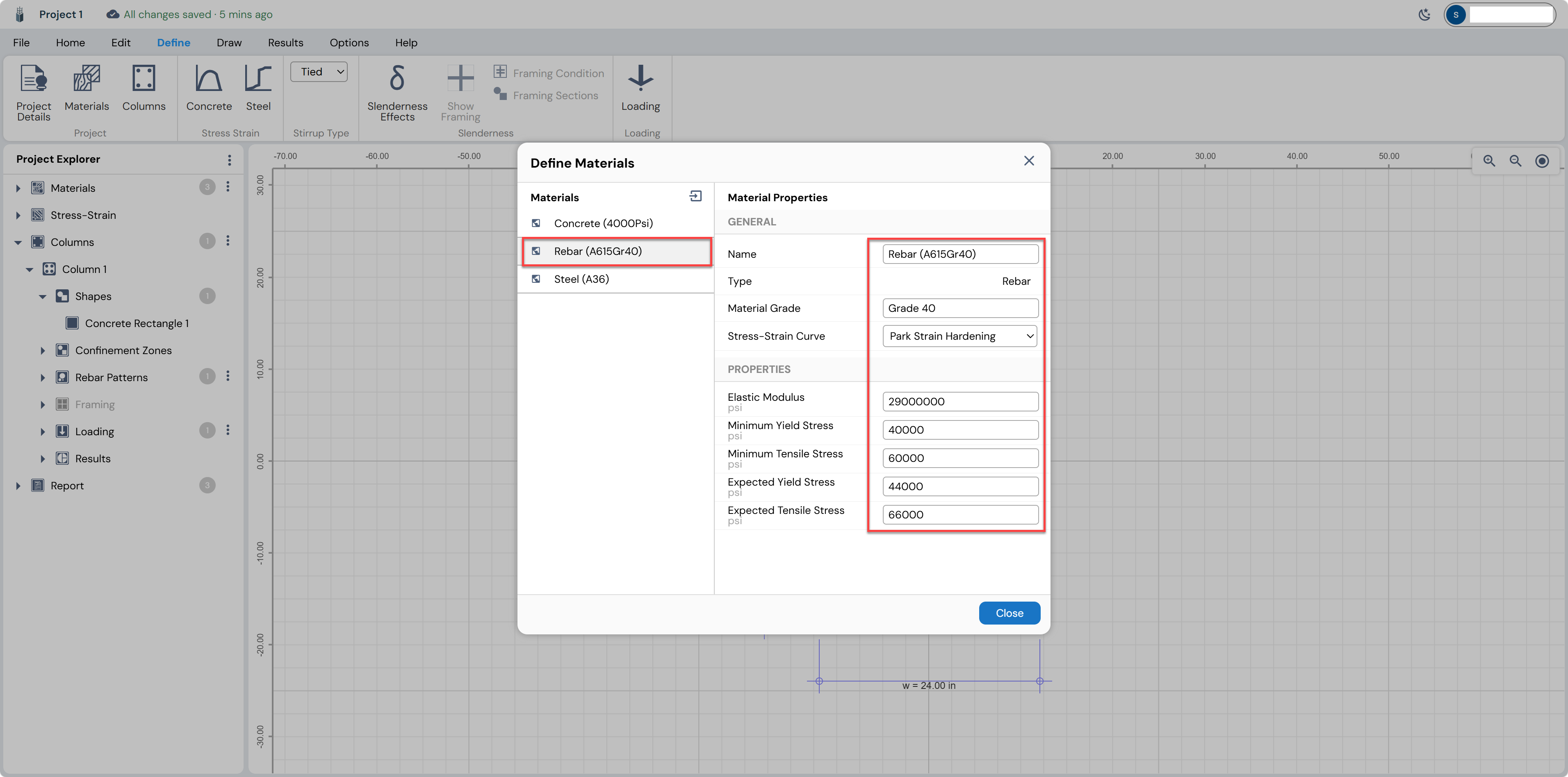
Next, define the reinforcing steel properties.
The available inputs include material grade, elastic modulus, minimum yield stress, minimum tensile stress, expected yield stress, and expected tensile stress.
For this example, enter f𝑦 = 60,000 psi and f𝑢 = 90,000 psi.
Then click “Close”.
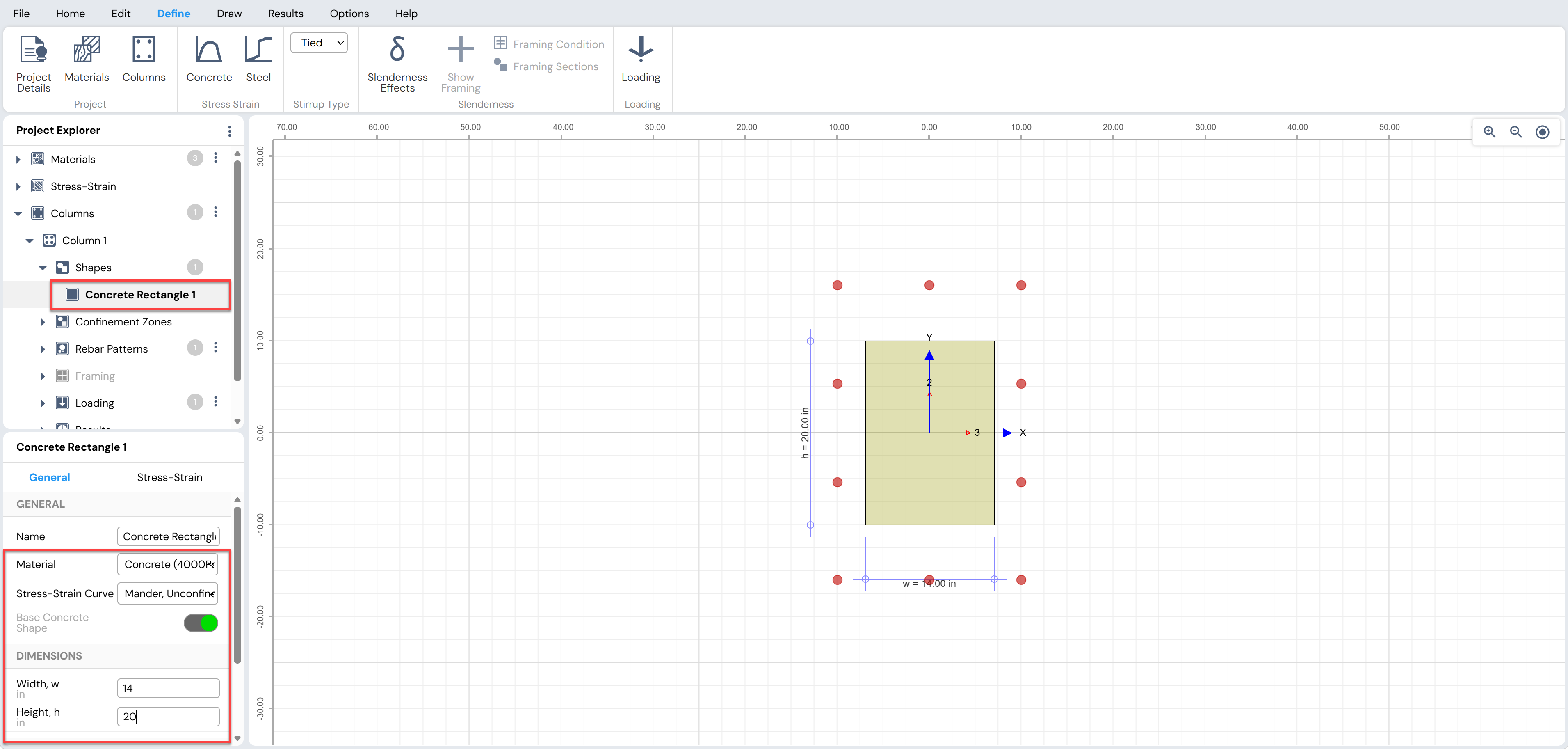
Click on “Concrete Rectangle 1” to define the section properties of the column.
Select “Concrete 4000 psi” as the section material.
Enter the cross-sectional dimensions: Width = 14 in. and Height = 20 in.
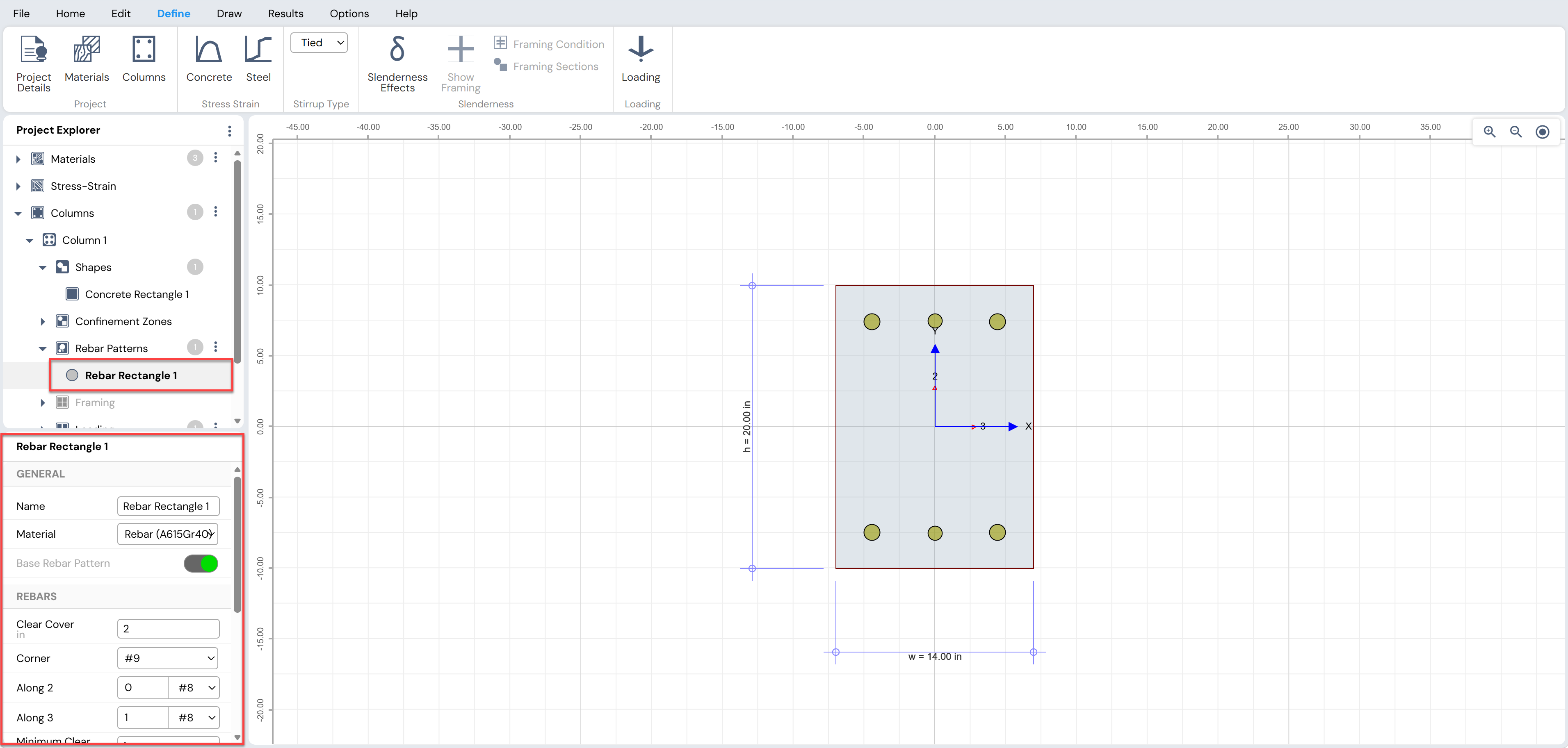
Click on “Rebar Rectangle 1” to specify the clear cover, rebar diameter, and rebar layout.
Select “Rebar (A615 Grade 60)” as the reinforcement material.
Set the clear cover to 2 in., then specify the number of rebars and select the bar diameter for the corner bars and the bars along the 2- and 3-directions.
3. Load Application
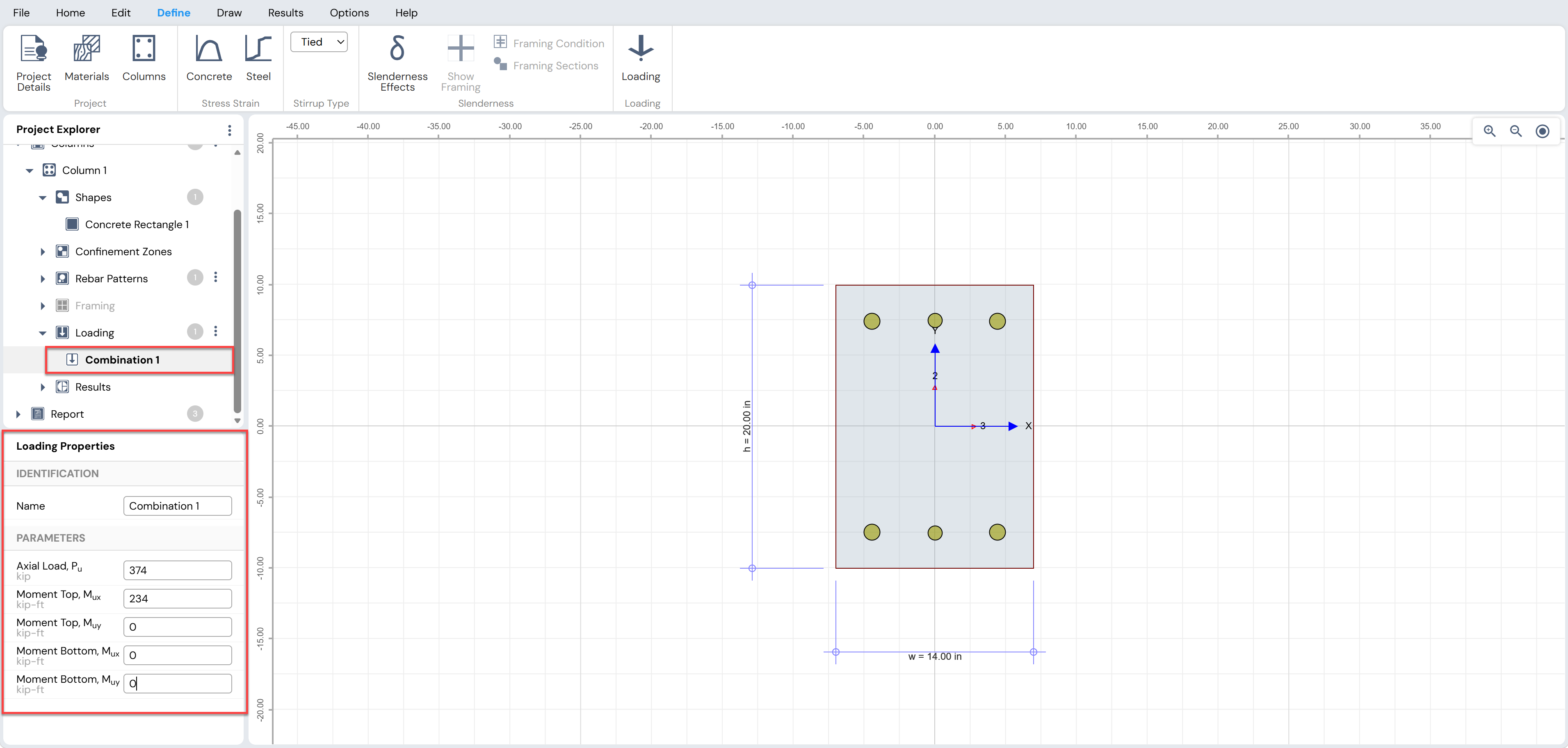
Enter the factored axial load and bending moment values.
These loads represent the design demand acting on the column and must be checked against the column’s strength capacity derived from the interaction diagram.
Click “Combination 1” and enter the load data: P𝑢 = 374 kip and M𝑢x = 234 kip–ft.
4. Analysis Results and Interpretation
4.1 Interaction Diagram
Select and enable “Interaction Diagram”.
The axial load–moment interaction diagram is generated based on strain compatibility and equilibrium of internal forces.
Each point on the curve represents a possible failure condition, allowing verification that the applied load combination falls within the safe capacity region.
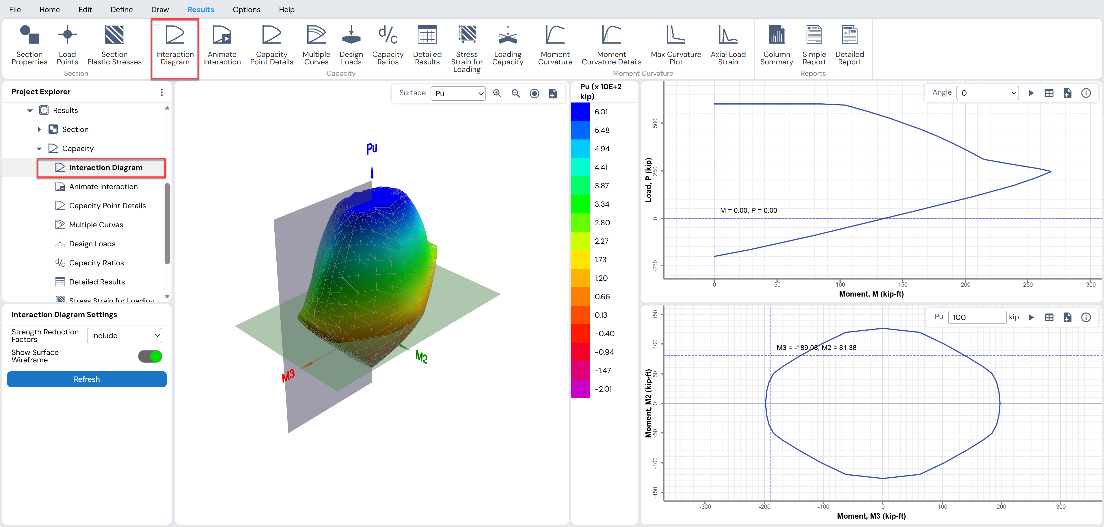
In the Load (P)–Moment (M) interaction plot, the closed curve defines the failure envelope of the column section. Any load combination plotted inside corresponds to a condition where the column has sufficient strength to resist the applied axial force and bending moment. Load combinations located outside the curve indicate overstress and structural inadequacy.
4.2 Detailed Results
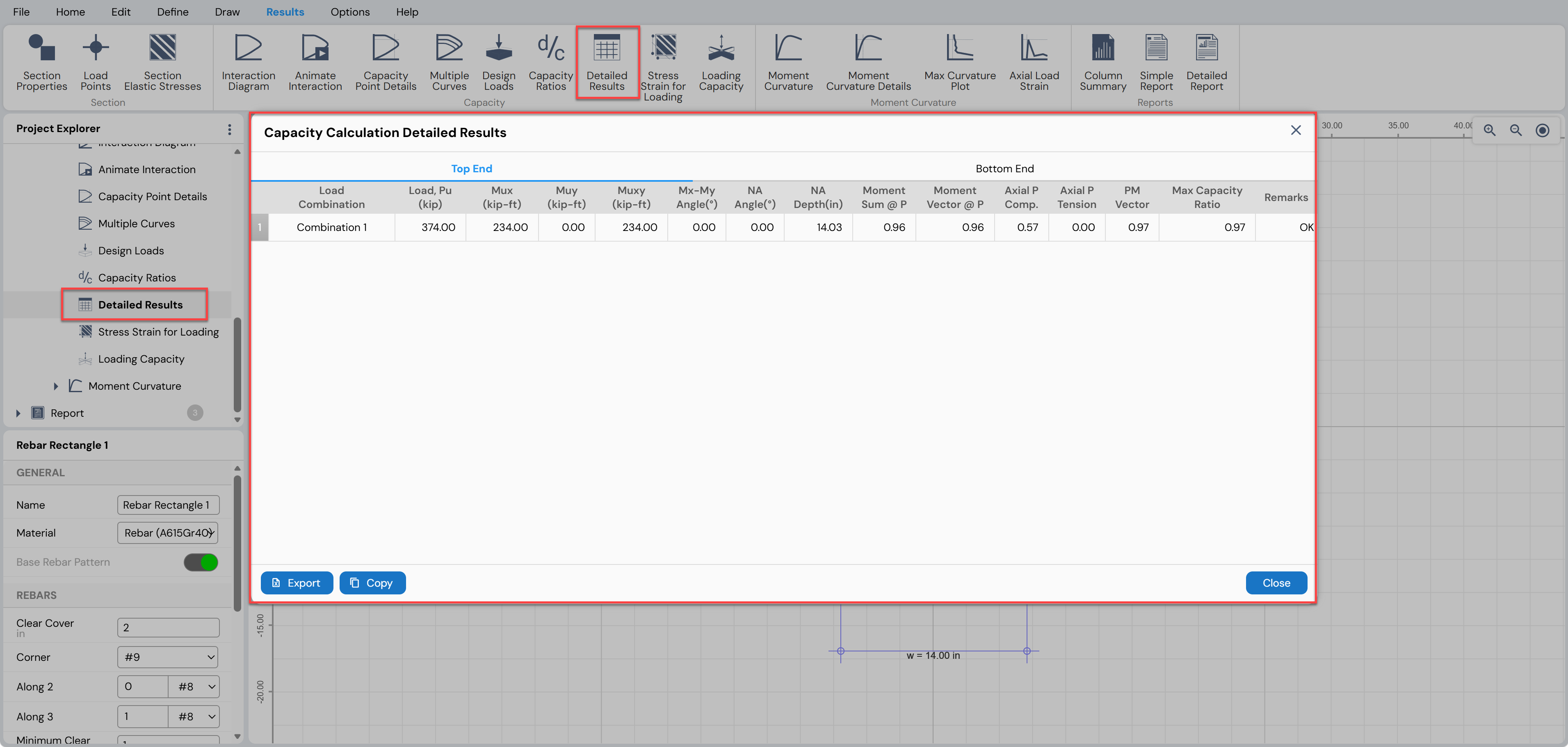
Select and enable “Detailed Results”.
The “Capacity Calculation Detailed Results” dialog presents the applied loads, maximum demand-to-capacity ratio, and a “Remarks” column indicating whether the column design is adequate.
Results are available for both the top and bottom ends of the column.
4.3 Stress Strain for Loading
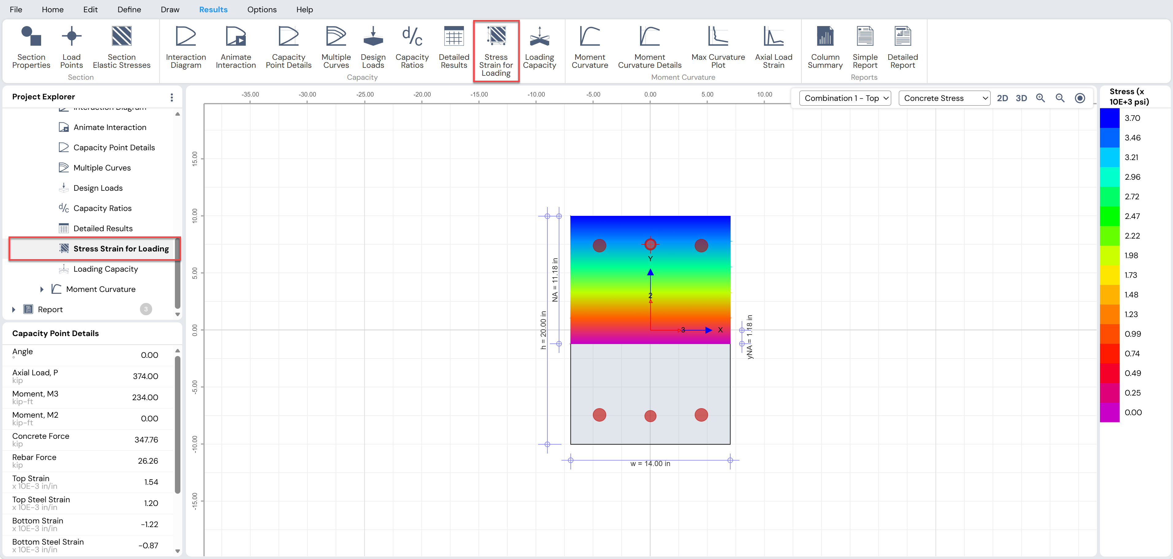
Select and enable “Stress Strain for Loading”.
The stress–strain output illustrates how concrete and reinforcing steel respond to the applied axial load and moment.
This information helps identify whether the column behavior is compression-controlled or tension-controlled, which directly affects the strength reduction factor.
The diagram also displays the neutral axis (NA) location.
The region above the NA line is in compression, while the region below is in tension.
4.4 Moment Curvature
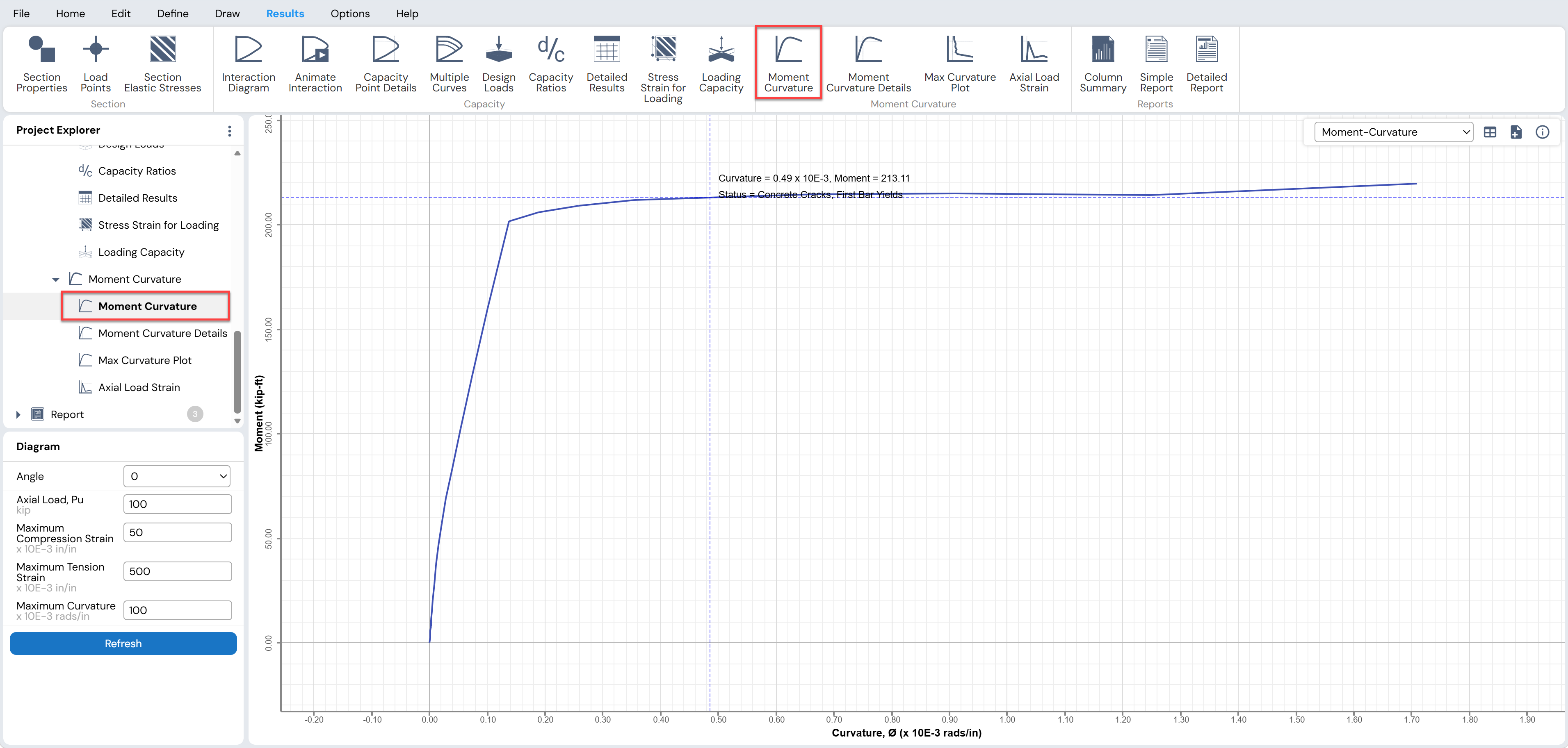
Select and enable “Moment Curvature”.
The moment–curvature curve represents the flexural stiffness and deformation capacity of the column section.
This relationship is important for understanding nonlinear behavior, ductility, and potential performance under increased loading.