


Merging and Subtracting
Worked Example
Introduction
This tutorial builds a rectangle with two semicircular ends and demonstrates the full Merge workflow, and then shows how Subtract option creates an inner opening from the merged polygon. Rebar patterns are placed at each stage to form a complete, analysis-ready cross-section.
Starting a New Blank Project
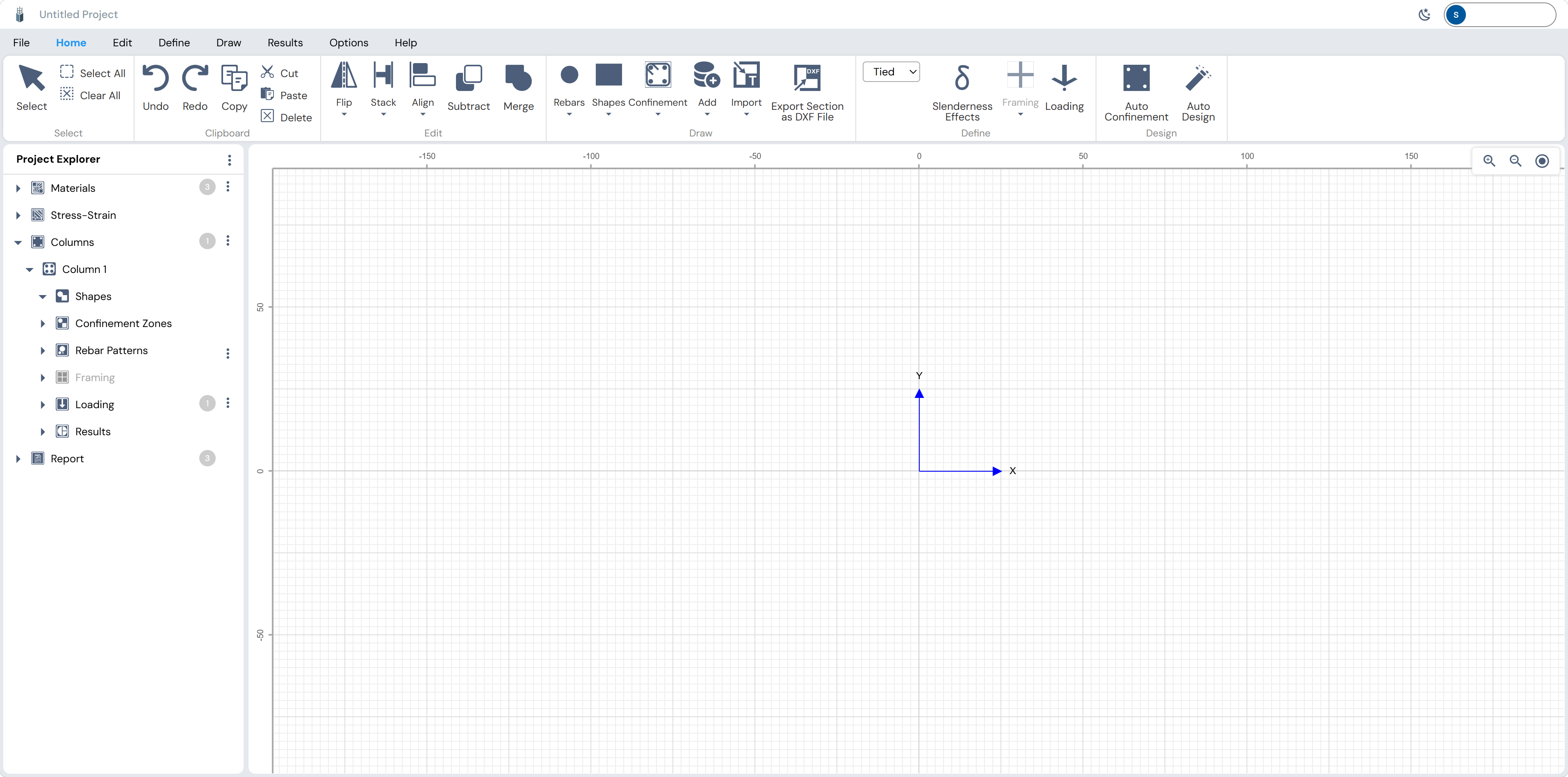
Navigate to column.eaglei.tech. On the home screen, click Blank under NEW COLUMN “Start with a blank model”. This opens the main canvas workspace with no shapes pre-placed: only the local X-Y axis is visible.

Creating a Section with Merge
A section will be drawn that consists of a rectangle with two semicircles capping each short end. Because Column Designer draws full circles, the workflow places a full circle at each end, overlapping the rectangle. Merge then fuses all three shapes into one smooth polygon.
Draw the Base Rectangle
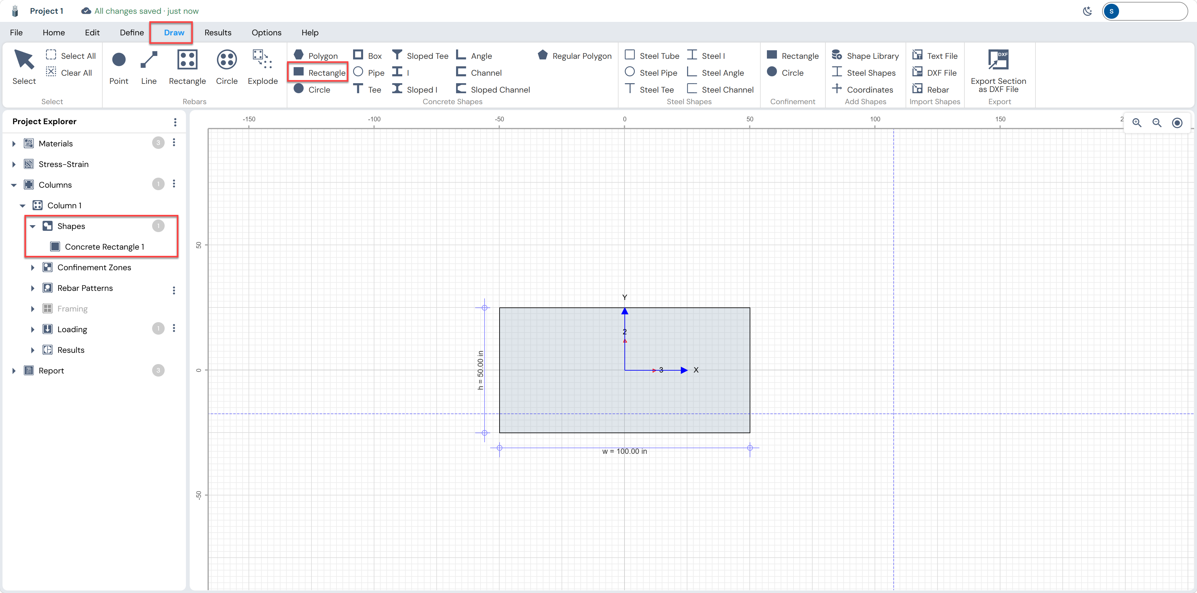
Click the Draw tab in the ribbon to open the drawing tools. Click Rectangle in the Concrete Shapes group.
Click and drag on the canvas to place the rectangle. While dragging, live dimension annotations appear. Release the mouse when the rectangle reaches the desired size, or fine-tune the exact dimensions afterwards in the properties panel.
The rectangle is saved as Concrete Rectangle 1 in the Project Explorer under Shapes. Click it to see and edit the exact dimensions in the left panel. For this tutorial, set:
| Parameter | Value |
|---|---|
| Width, w | 100 in |
| Height, h | 50 in |
| Position X | 0 in |
| Position Y | 0 in |
Draw the Left Circle
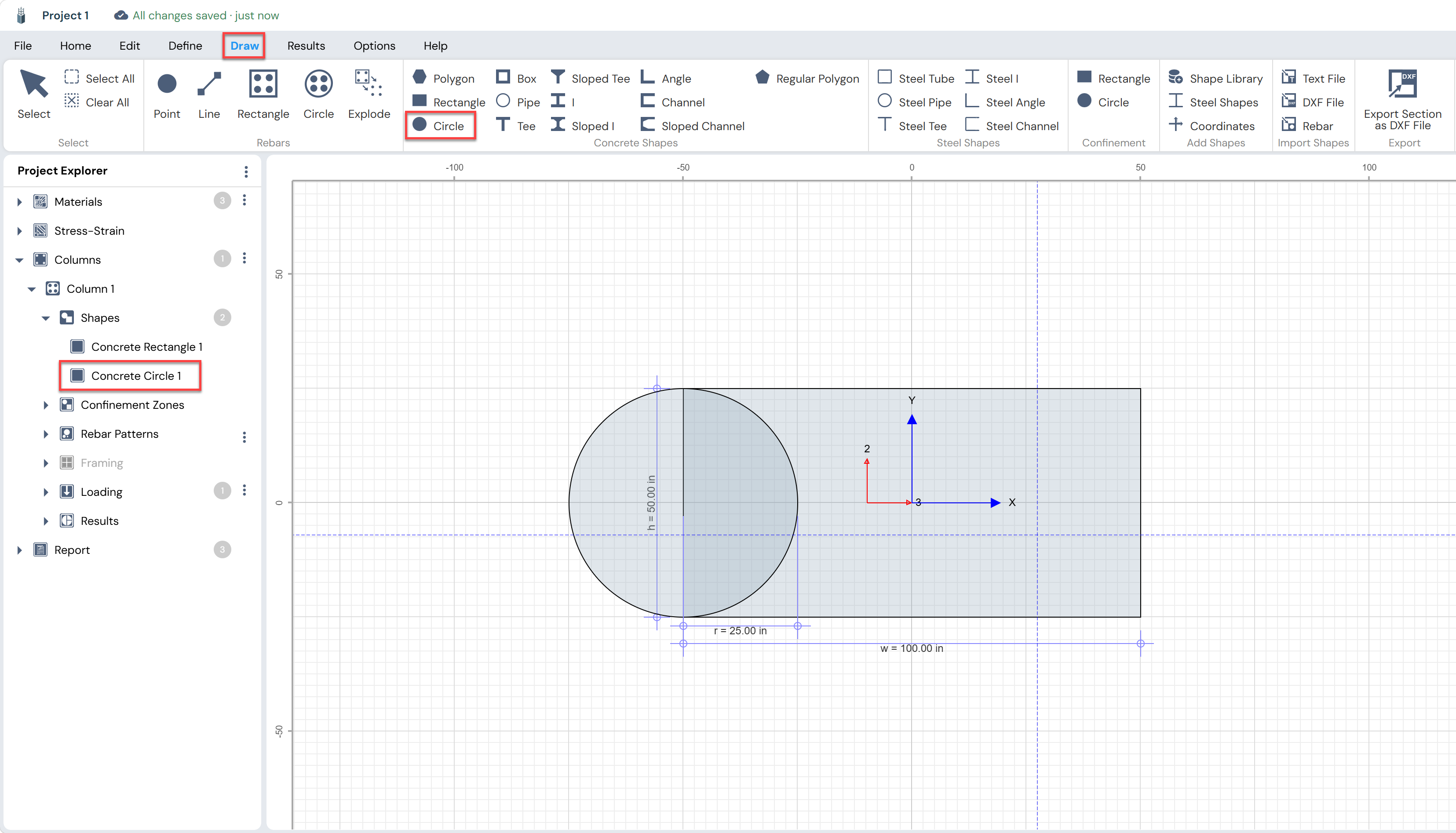
Still in the Draw tab, click Circle in the Concrete Shapes group. Draw a circle centered on the left edge of the rectangle so that the circle’s right half overlaps the rectangle, and the circle’s diameter equals the rectangle’s height.
Draw the Right Circle
Draw a second circle with the same radius, mirrored to the right end of the rectangle.
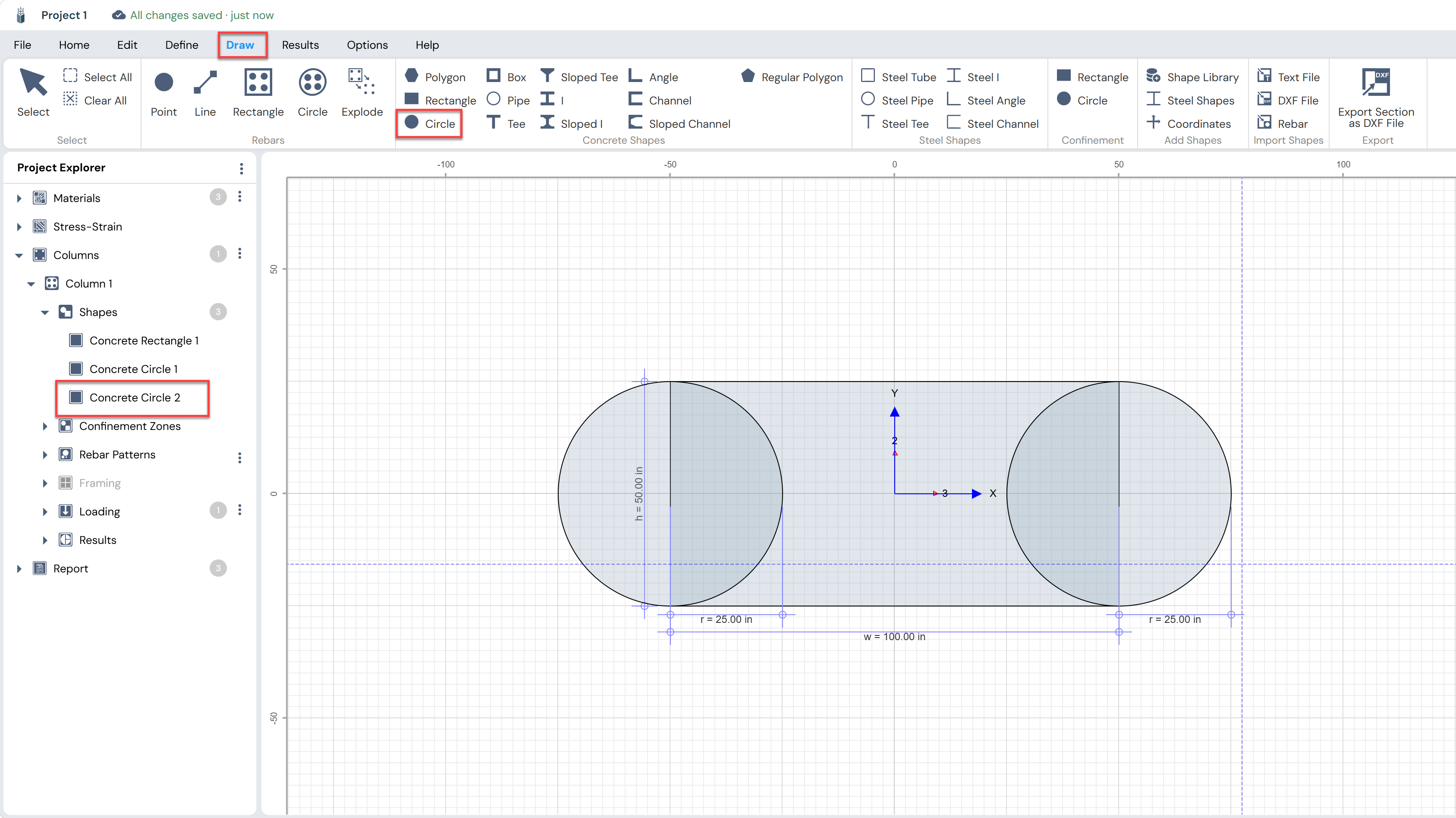
At this point the Project Explorer shows three shapes under Shapes: Concrete Rectangle 1, Concrete Circle 1, and Concrete Circle 2. Each shape is independently editable but overlapping on the canvas.
Select and Merge All Shapes
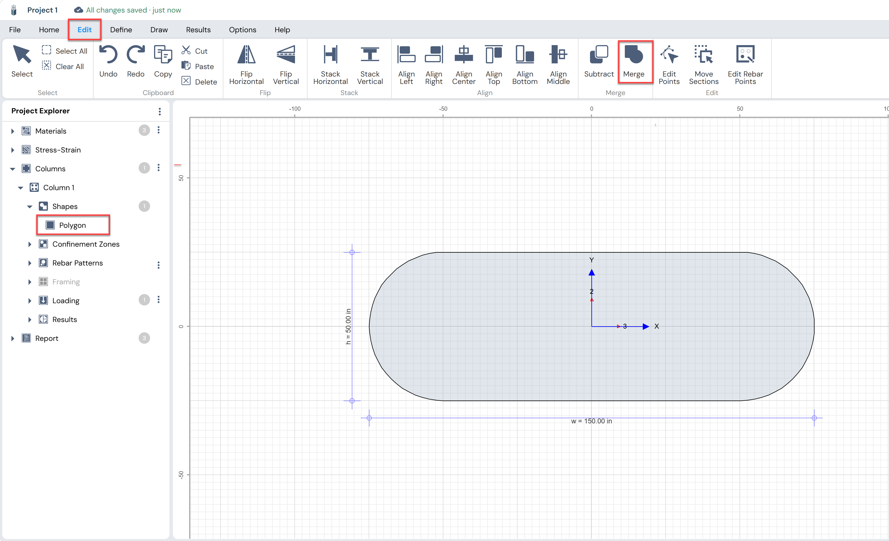
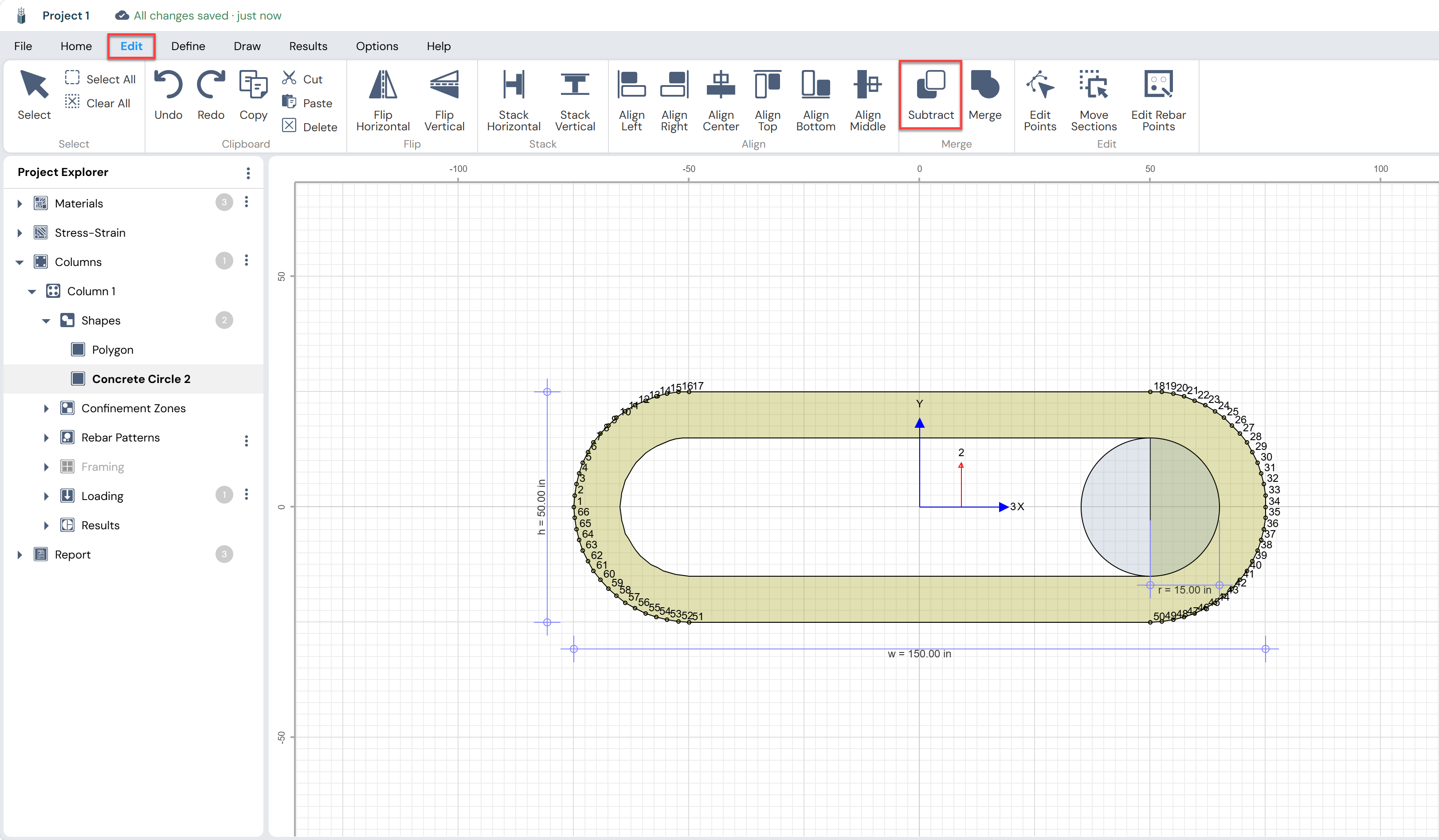
Switch to the Edit tab in the ribbon. The Edit tab reveals the functions: Subtract and Merge. Before Merging, all shapes must be selected simultaneously. Click the Merge button in the Edit ribbon.
The Project Explorer now shows a single Polygon under Shapes.
Creating a Hollow Section with Subtract
Subtract removes one shape’s area from another. This is used to create hollow box sections, pipe voids, chamfered corners, and any opening within a larger section. The workflow is: place the cutting shape (the void shape) over the base shape, select both, then click Subtract.
Draw the Inner Void Rectangle
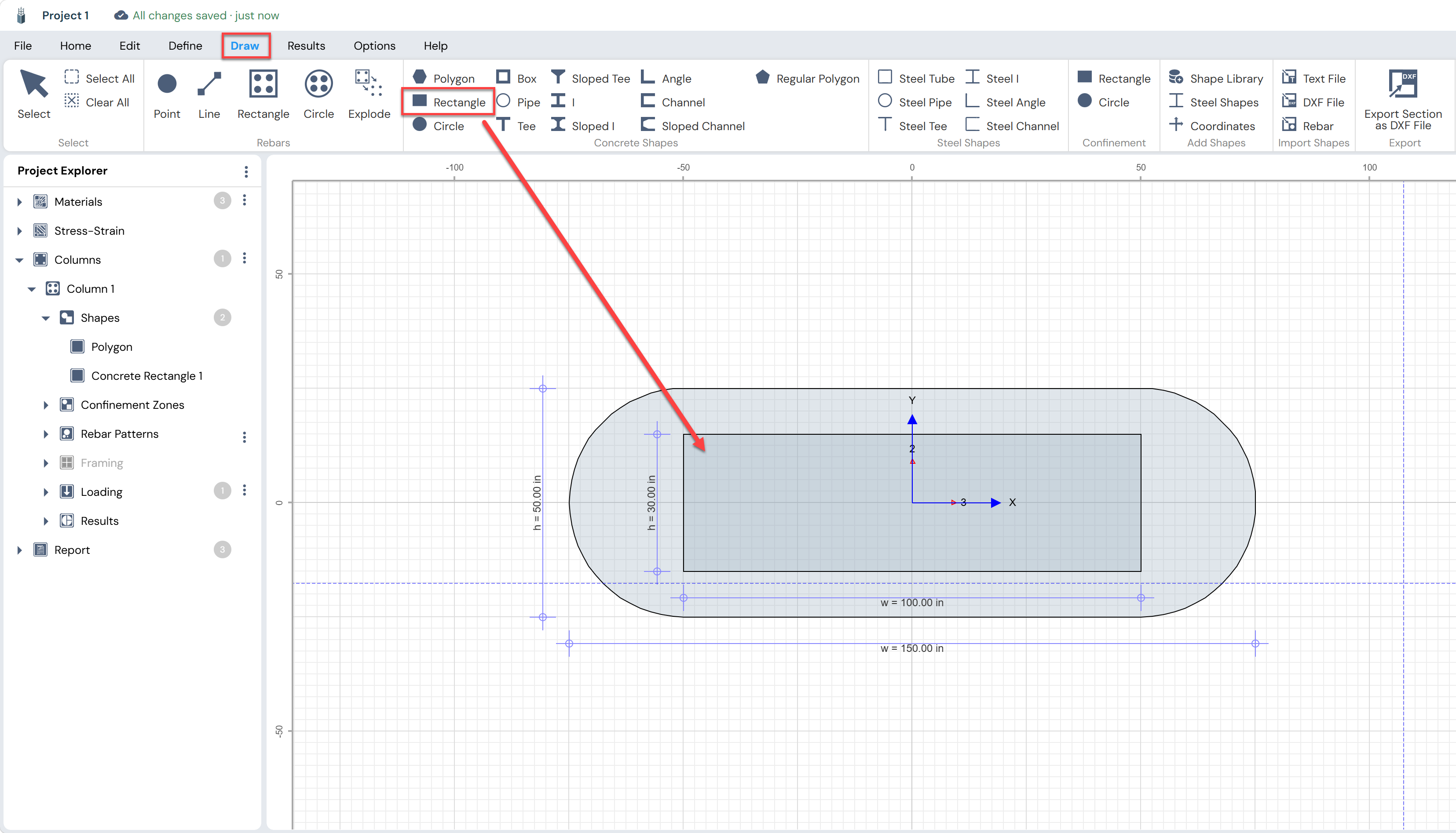
The merged polygon from Part 1 is the base. Now draw a smaller rectangle inside it to represent the void (hollow interior). Switch to the Draw tab and click Rectangle.
Position and size the inner rectangle with a uniform wall thickness on all four sides. For a 10 in wall.
Select Base Shape, Then Void Shape
Selection order matters for Subtract. The correct approach in Column Designer is:
Click the outer base shape first (the Polygon).
Then hold Shift and click the inner void shape (the new rectangle).
Subtract
With both shapes selected, click the Subtract button in the Edit ribbon.
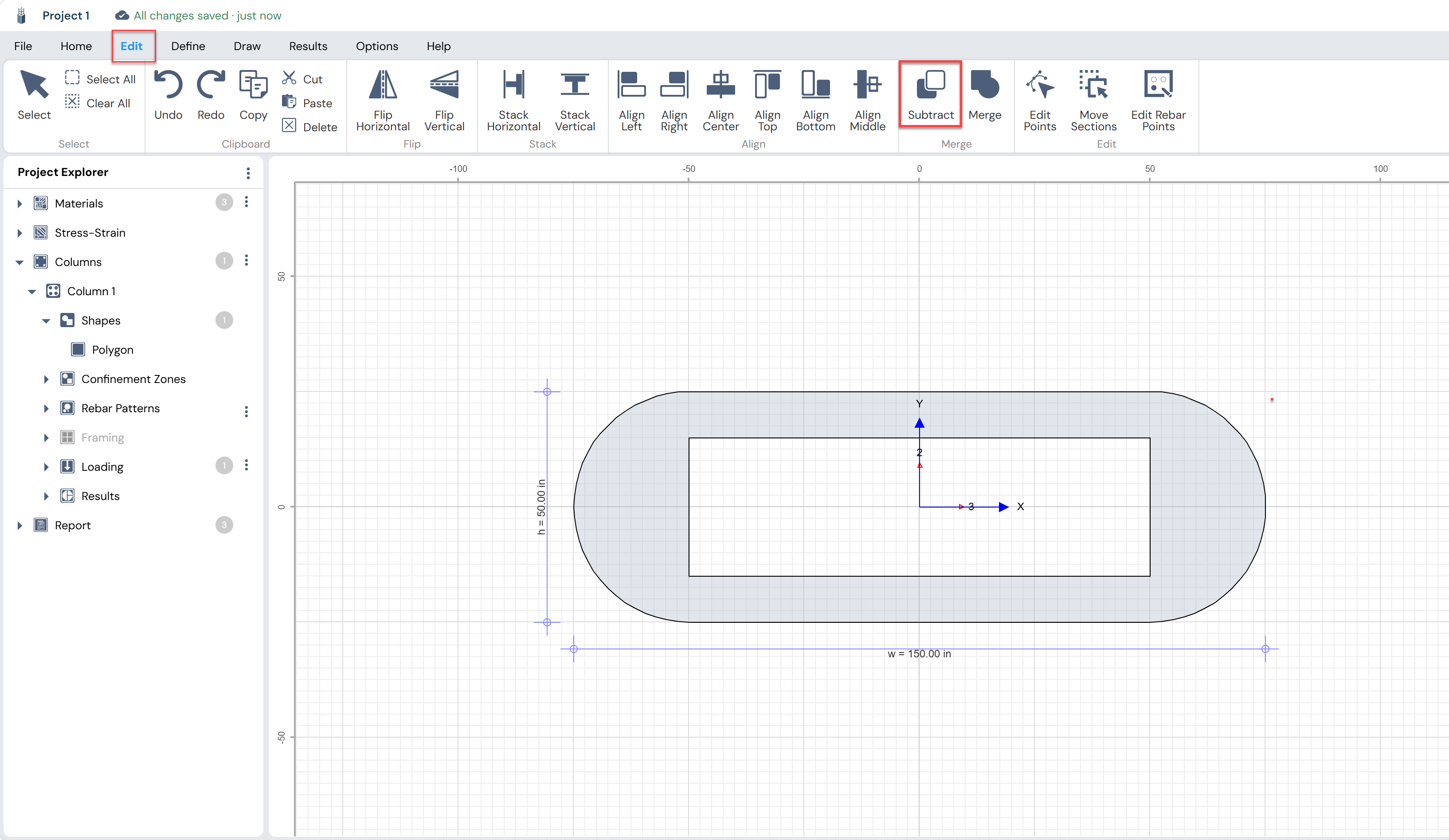
The Project Explorer again shows a single Polygon node. The inner void is represented as a hole in the polygon.
Repeat similar steps using circular shape to subtract the concrete area on the left and right side of polygon.
Adding Rebar to the Composite Section
After creating the composite polygon, rebar patterns must be placed on the final shape. Column Designer supports several methods: drawing rebar patterns directly on the composite shape, or using the Explode tool to break apart individual Circle/Rectangle rebar patterns into independent Rebar Points that can then be repositioned precisely.
Drawing a Rebar Rectangle Directly
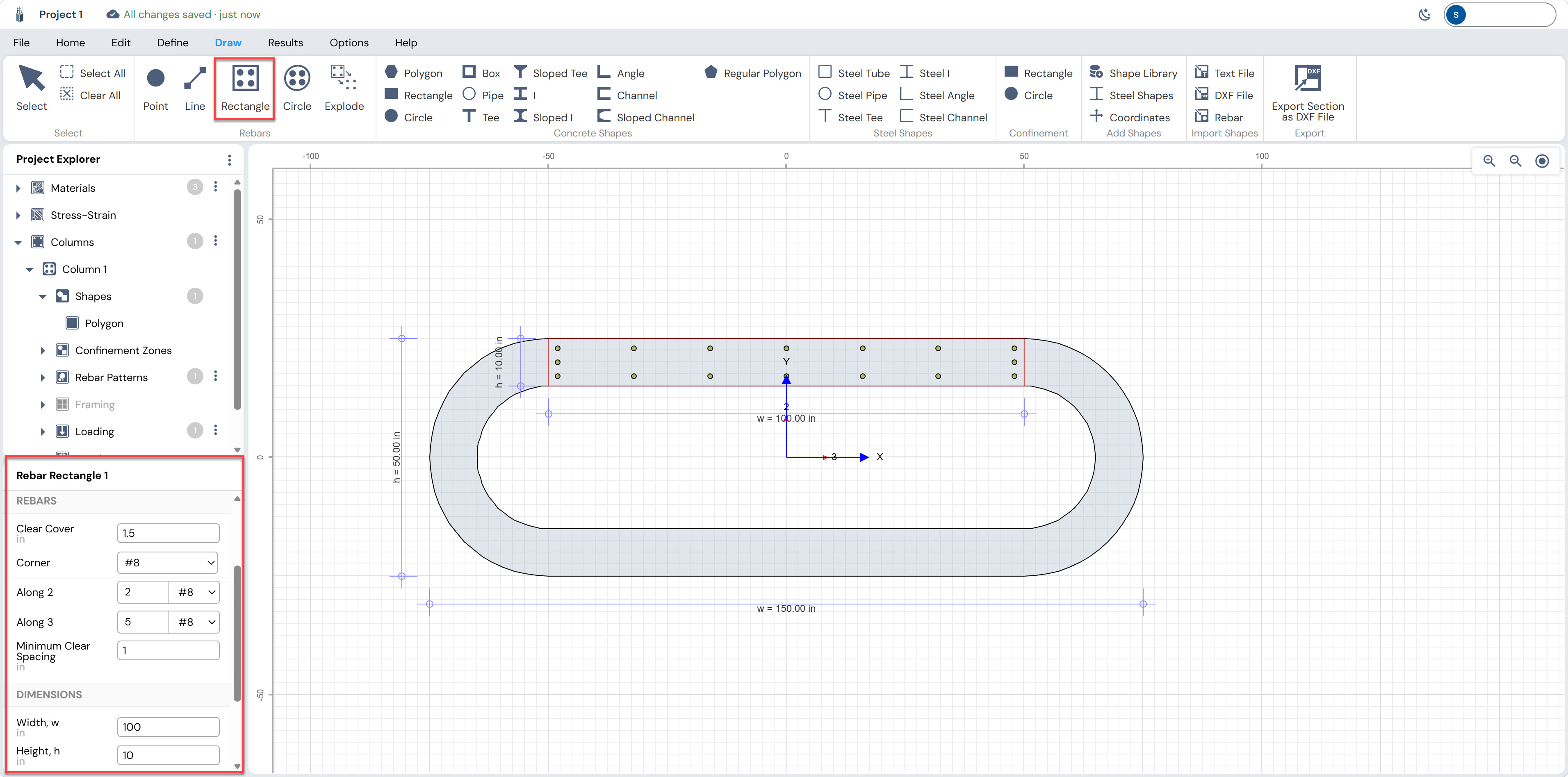
Switch to the Draw tab. In the Rebars group, click Rectangle (the rebar-rectangle tool, distinct from the concrete Rectangle). Draw a rebar rectangle directly inside the straight wall of polygon. This places rebars along the four sides of a rectangular layout at a specified clear cover.
Adding Circular Rebar Patterns at the End Caps
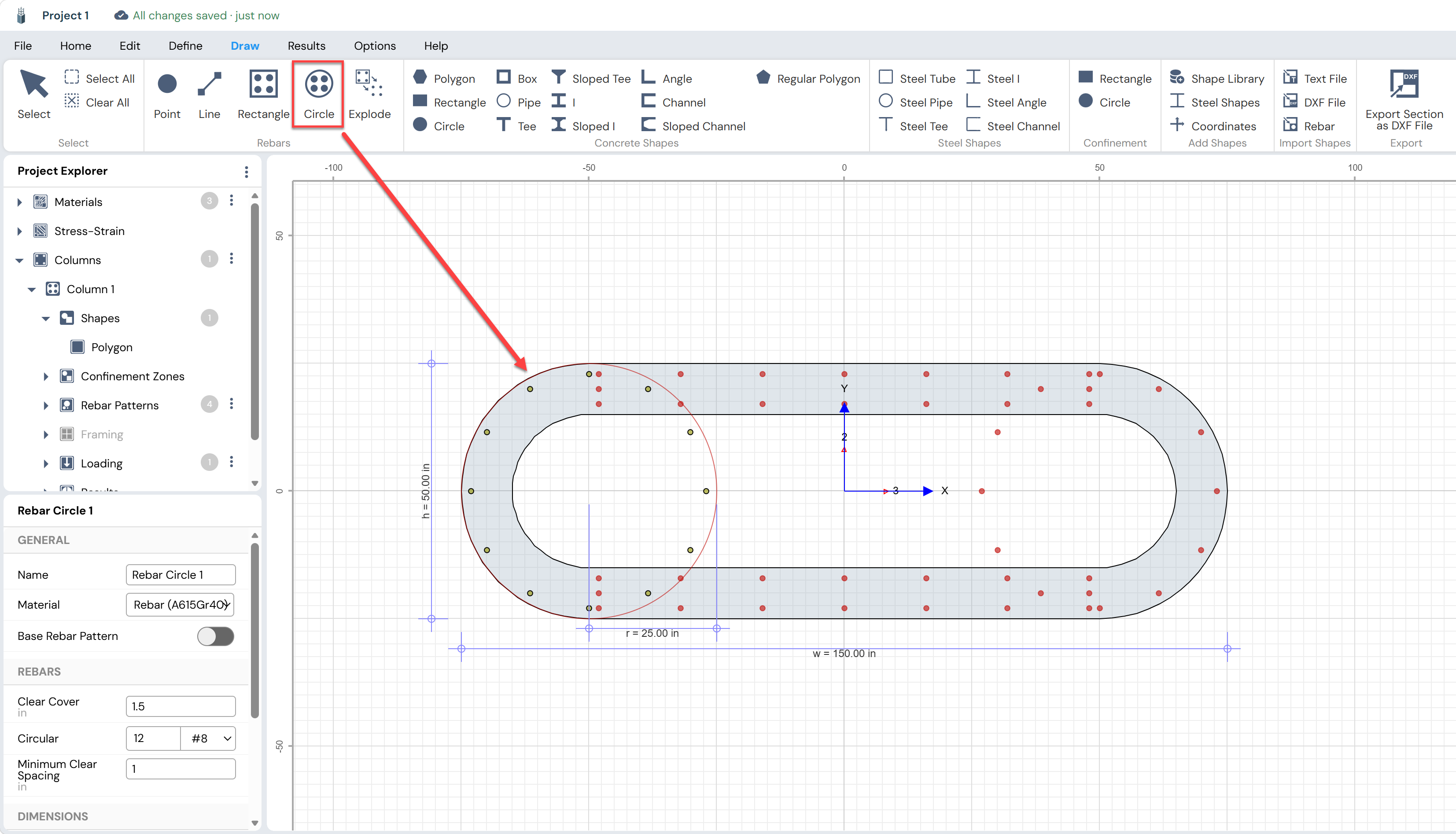
The semicircular ends of the section require circular rebar patterns. Switch to the Draw tab and use the Circle rebar tool (in the Rebars group) to place circular rebar rings at both ends.
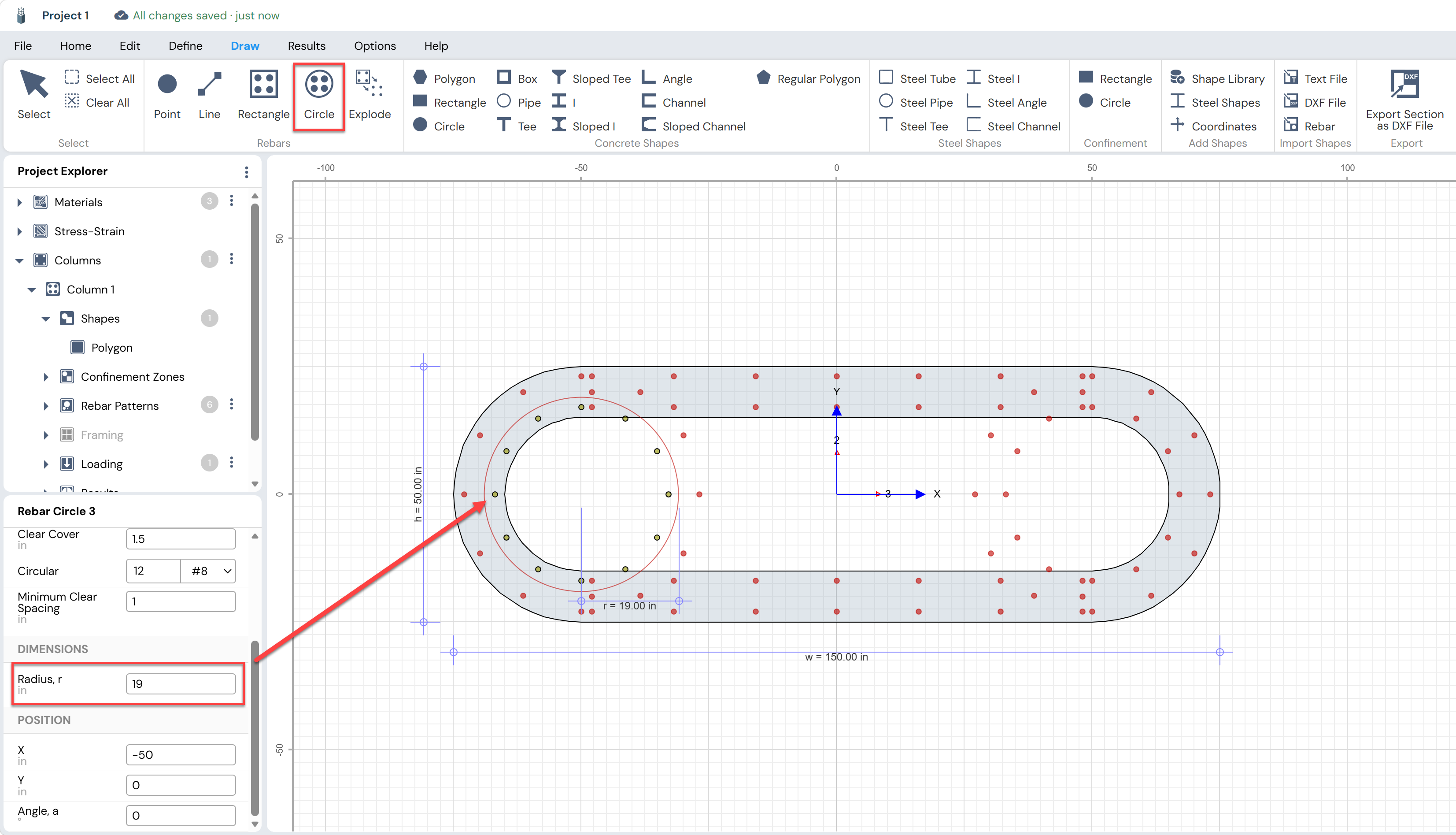
Similarly, draw another circle of inner rebars and adjust its radius from the property panel.
Using Explode to Convert Patterns to Individual Points
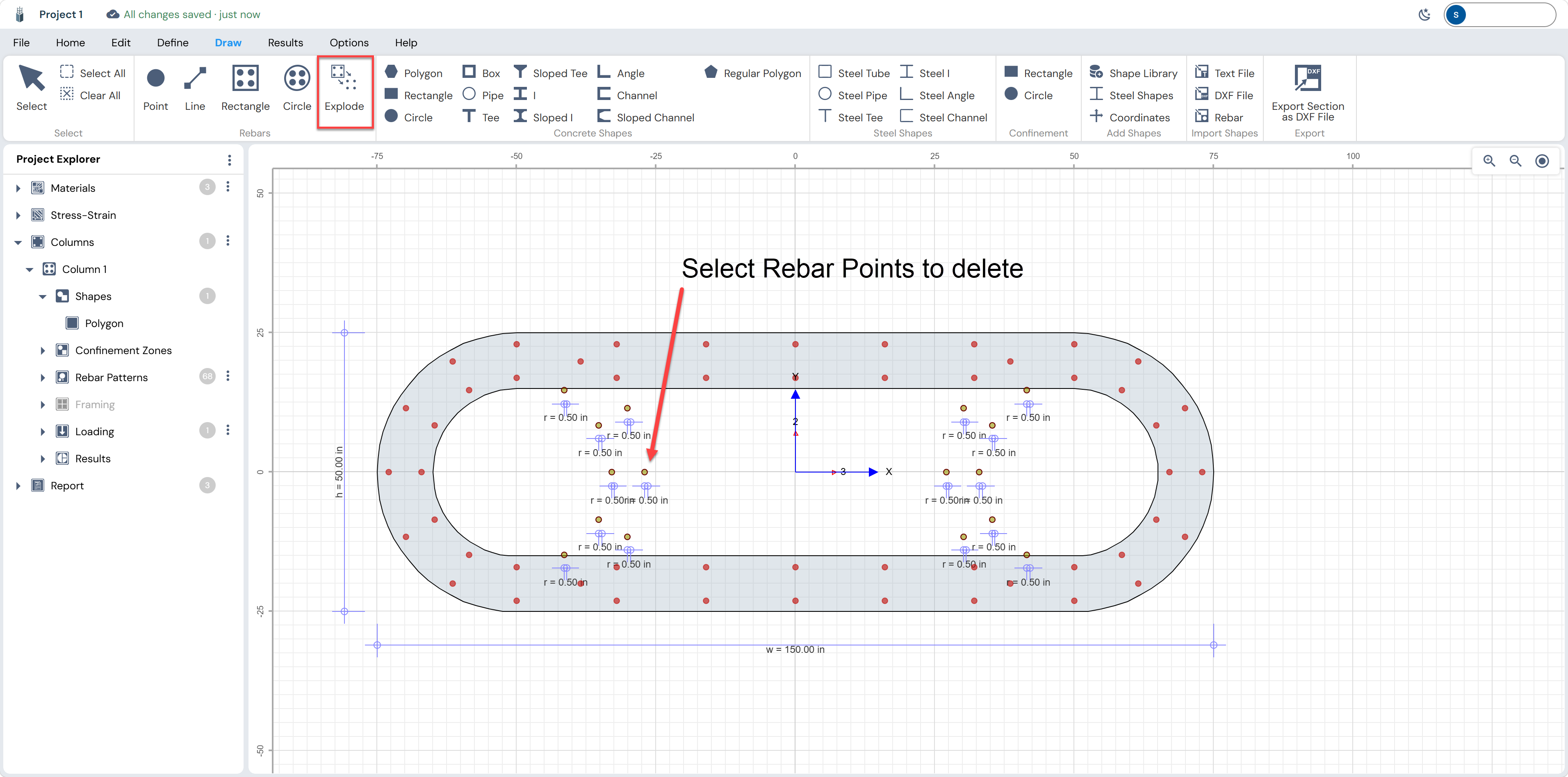
When a rebar pattern (Circle or Rectangle) is used as a seed, all bars share a common definition. The Explode tool breaks the pattern into individual Rebar Point nodes, each independently movable and resizable which is ideal for fine-tuning positions on non-standard shapes.
To Explode a rebar pattern: select the Rebar Circle or Rebar Rectangle node on canvas, then click Explode in the Draw tab. The pattern is dissolved into individual numbered Rebar Point nodes visible in the Project Explorer.
After the circular and rectangular patterns are exploded, the extra rebar points can be simply deleted.
Final Section
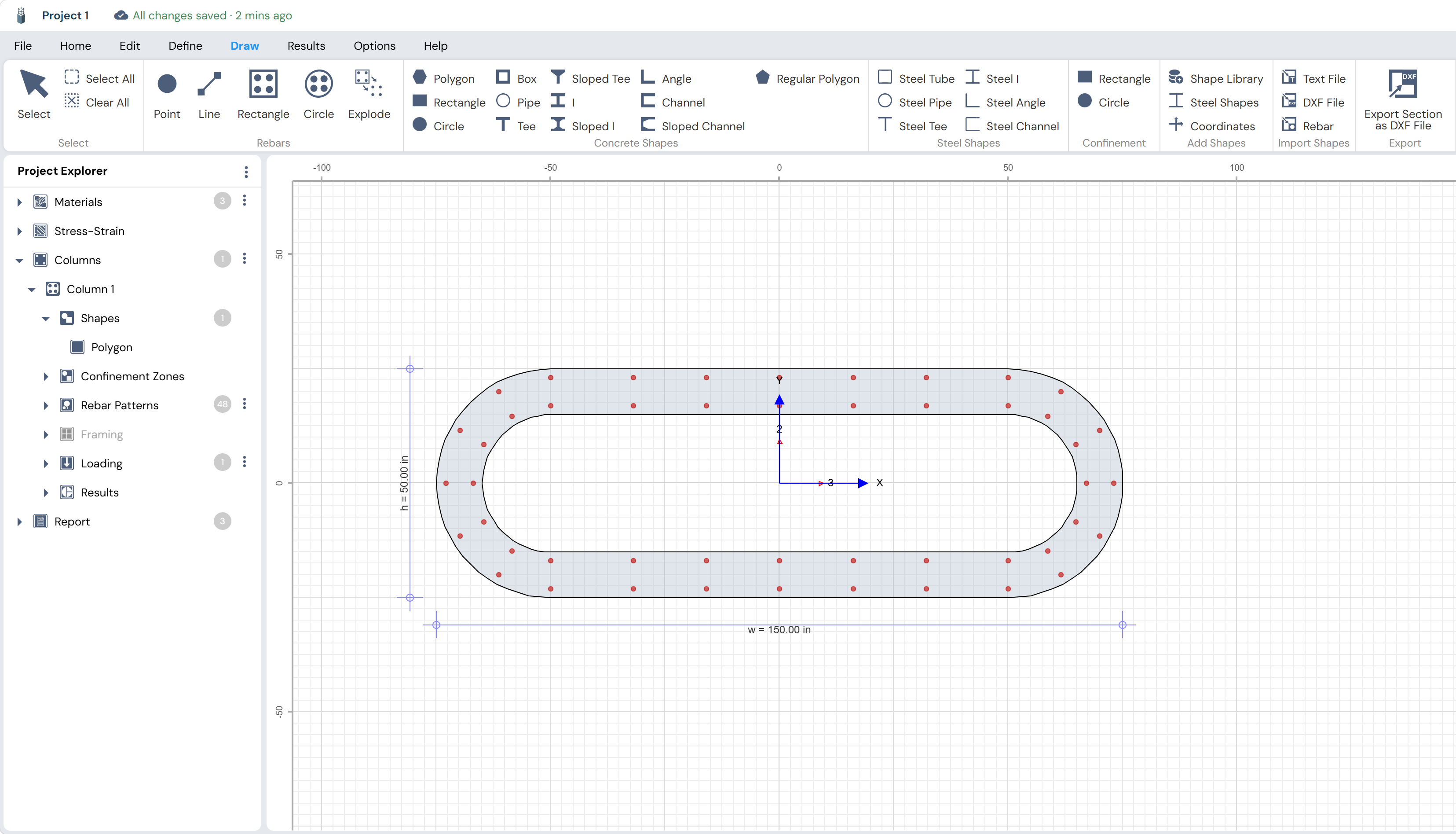
The completed composite section consists of the hollow polygon (150 in × 50 in) with multiple rebar patterns placed on the concrete wall, providing full perimeter reinforcement around the hollow void.
| Next step: With the composite section built, proceed to the Define tab to set units and design code, add loading, and use the Results ribbon to compute interaction diagrams, capacity ratios, and reports. |